The Ponsel sensors sold by Ayyeka include the following part numbers:
- SE00017-SER
- SE00018-SER
- SE00019-SER
- SE00020-SER
Contents
Prerequisites
Step 1. Get Connected!
Step 2. Select Port
Step 3. Connect to the Sensor
Step 4. Calibrate the Data Stream
Step 5. Define the Reference Value for the Sensor’s Parameter
Step 6. Define a Different Reference Value
Step 7. Reset the Sensor
Prerequisites
Computer with the following software installed:- Microsoft Windows operating system
- Laptop with a USB port
- Calsens software (provided by Ayyeka)
- Access to the FAI Pro or FAI Local with Administrator or Owner user role permissions
- RS485-USB Adapter (Ayyeka part number WA00244 for US wall plug, or WA00254 for Europlug).
Step 1. Get Connected!
- If you haven’t already done so, disconnect the sensor from the Wavelet.
- On your Microsoft Windows PC, open the Device Manager. A list of all connected devices
is shown. - Connect the sensor to the M12 female field attachable connector and connect the wall
plug power supply to an electric wall socket. If a wall plug connection not be made (e.g.
the calibration must be performed in the field), connect the sensor to your PC using an
RS485-USB adapter and a 12VDC supply and ground for the sensor according to the
sensor wiring diagram. This involves opening the field attachable connector and
replacing the supply and ground connections of the wall plug supply with a different
power source. - With the Device Manager application open, plug in the RS485-USB plug to your PC. The
sensor is listed as a new device. Take note of the ports (COM and LPT) for the new device (sensor) that appears. If you do not find it on the first try, disconnect the USB
plug, and then try again.
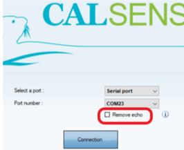
Step 2. Select Port
- Start the Calsens 1.3 application.
- In the Select a port list, select Serial port.
- In the Port number list, select the right COM based on Step 1 above.
- Clear the Remove echo check box, and then click Connection.
Step 3. Connect to the Sensor
- Click Scan.
- Select the sensor, and then click Calibrate. Calsens starts to connect to the sensor.
Step 4. Calibrate the Data Stream
In the Selection of the parameter to calibrate window, do the following steps:- From the Operator drop-down menu, select CALSENS_USERS.
- Select the data stream that you need to calibrate.
- Set the External Temperature compensation value to the measured temperature of
- the room, in Centigrade. In our example, the room temperature is 22.
- Click Calibrate.
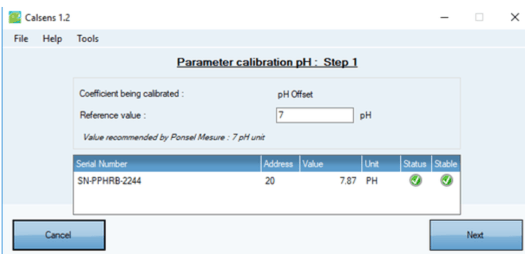
Step 5. Define the Reference Value for the Sensor’s Parameter
Most of the parameters can be calibrated in two steps: an offset and a gradient. All the
calibration steps are made from the same model - a reference value must be filled in. Typically,
a default value is given.
- Type in the Reference value for the parameter. In our example, we’re using the pH
offset of 7.00 as our reference, so we’ll type in 7. - Wait to get a stable value from the sensor, and then click Next.
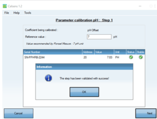
An Information window opens to indicate that the first calibration reference was executed
successfully.
Step 6. Define a Different Reference Value
- Rinse the sensor thoroughly with distilled water, and then dry it with a soft cloth.
- Repeat the previous step, but now type in the reference value for a different parameter.
In this example, we now type in the reference value for pH gradient, and we’ll use the
pH value of 4.00 instead of 7.00.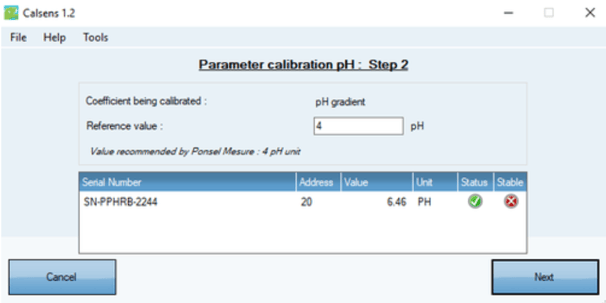
- Click Next. The Summary window opens to display the results for the sensor for both pH
Offset and pH Gradient.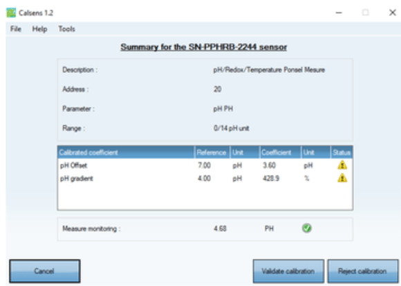 The summary displays the main information concerning the sensor and its calibration. The
reference, coefficient values, and their status are displayed. A real time monitoring with the
new coefficients applied is to validate the measurement. - Click Validate calibration, Reject calibration, or Cancel. If you click Cancel, the calibration is stopped and you return to the Parameter Selection window (step 4).
Step 7. Reset the Sensor
After disconnecting the sensor from your PC, a command must be written to specific
register of the sensor.
- Log into the FAI Pro or FAI Local UI with your credentials.
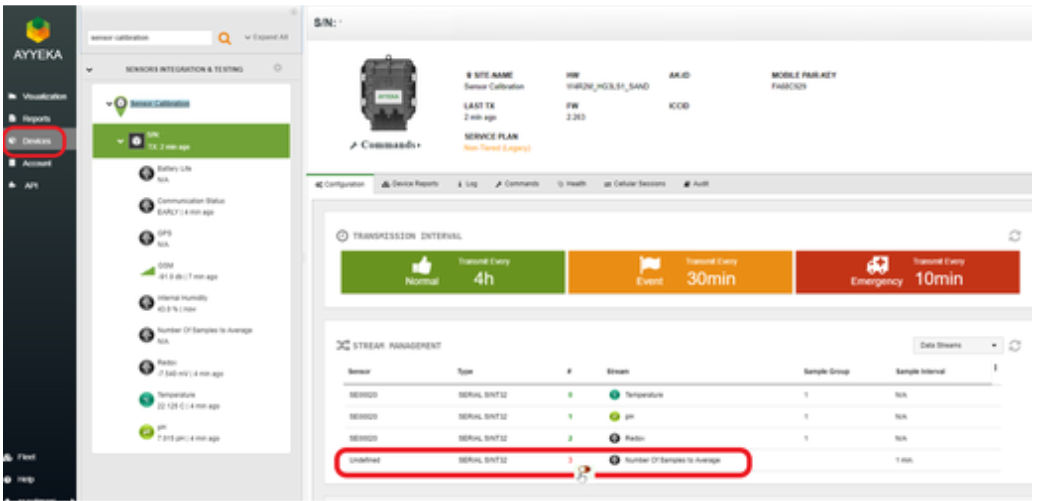
- In the left pane, click the Devices tab.
- In the Sites Tree pane shown immediately to the right of the left-hand sidebar, select the
Site associated with the device or search by device serial number. In our example, we
have a Site called Sensor Calibration. - Click the name of the device under the site. The Configuration tab opens in the right
pane. - In the Stream Management section of the Configuration tab, all streams and channels
are listed. The channel number in green in the # column indicates an active channel,
while a channel number in red indicates an inactive channel. - In our example, channel 0 (Temperature), channel 1 (pH), and channel 2 (Redox) are active, while while 3 (Number of Samples to Average) is inactive.
- Before reconnecting the sensor to the device, we must deactivate all active sensor channels associated with data measurement (0, 1 and 2 in our example). Hover your mouse pointer over the channel number (in our example, over channel 0, 1, and 2). A slider button is displayed. Move the slider to the left. A confirmation message to deactivate the channel is shown.
- Click Submit. The command to deactivate the channel is created.
- Repeat steps 7 and 8 for all sensor channels associated with data measurement (in our case, 1 and 2). Note: The channel becomes inactive only after the next device transmission and
successful execution of the commands. - Confirm the commands to deactivate the sensor channels were executed, which is indicated
by 100% in the Commands tab.

-
Reconnect the sensor to the device.
- Hover with your mouse pointer over the channel number associated with the data stream
“Number of Samples to Average” (in our case, over channel 3). A slider button is displayed.
Note: For devices configured with multiple Digisens sensors, the “Number of Samples to Average” is indicated for each sensor type with a parenthetical indication. for example, Number of Samples to Average (PHEHT) for the pH/ORP sensor, Number of Samples to Average (OPTOD) for the dissolved oxygen sensor, etc.
Hover your mouse pointer over the channel number associated with the data stream
“Number of Samples to Average” (in our case, over channel 3). A slider button is displayed.
13. Move the slider button to the right. A confirmation message to activate the channel opens.
14. Click Submit. The command to activate the channel is created.
15. The channels for sensor measurement (channel 0, 1, and 2 in our example) can now be
reactivated, and the channel associated with the stream Number of Samples to Average
(channel 3 in our example) can now be deactivated as per the instructions above.
Note: The channel becomes active only after the next device transmission and successful execution of the command.