Configure the Agent for CSV Output Files
Configure other Agent parameters (Metadata, Serilog, Logging, StoreDumps)
Integrate Raw Value data with SCADA
Configuring devices for MQTT communication
Stopping, Starting, and Uninstalling the Agent
Information About Popular MQTT Brokers
CSV parameters in apsettings.json
DNP3 parameters in appsettings.json
More DNP3 parameters in appsettings.json
MQTT section in appsettings.json
Metadata parameters for CSV and OPC UA
Serilog area in appsettings.json
StoreDumps area in appsettings.json
Prerequisites
You must have a basic understanding of MQTT. To learn about MQTT basics, features, and to watch video tutorials, see MQTT Essentials.
You must have the specifications documentation for the sensors that sample the data. Information about the communication protocol that the sensor uses is needed when you integrate Raw Value data into your SCADA system.
An MQTT Broker must be installed and configured according to the following points:
-
MQTT Broker must be accessible from outside and from inside your network.
-
Open port 8883 (secured) in the MQTT Broker’s host machine in the Firewall. You might also want to open port 1883 (unsecured) or other ports, according to your use case.
-
MQTT protocol with TLS communication must be enabled – certificates must be signed (CA or self-signed), and the Broker must be configured to use them.
-
You must know the address and port number of the MQTT Broker’s host machine.
-
If the Broker is configured to use several usernames and passwords, you must know those credentials.
Wavelet devices requirements:
-
The devices must have Firmware version 2.29x or newer.
Agent requirements:
-
The host computer must have a Microsoft® Windows® Server 2012, 64-bit or Windows 10 platform, 64-bit installed.
-
Contact support@ayyeka.com to get the Agent .MSI package installer file. Copy the installer file to your local computer, and then run the installer.
-
The Agent must be able to communicate with the MQTT Broker port (the default ports 8883 and, if needed, 1883)
-
The Agent must have read-write access to your file systems.
-
Microsoft .NET 5 must be installed on the host computer.
Configuring FAI Lite
In this section, you’ll configure your MQTT Broker to communicate with both the Wavelet device and the Agent. You’ll also configure the Agent either to work with your SCADA system or to export data as CSV files on your local computer.
-
Go to the directory where you installed the Agent.
-
Open the appsettings.json file with a text editor.
- Edit DeviceQueueItems according to your needs.
Each device queue holds items (data samples and device metadata) from each transmission. When the number of items reaches the value that you define (the queue is full), the Agent stops receiving information from the MQTT Broker until the queue is no longer full.
4. To send values to CSV output files, configure the Agent for CSV output files.
In the CSV area, edit parameters to format the file, partition data into directories and files, define file naming conventions, and filter data. For parameter details, click CSV parameters in apsettings.json.
5. To send values to DNP3 client, configure the Agent for DNP3.
-
- Go to the DNP3 area. Edit the following parameter values to configure the number of core threads and to define the template file that will map each channel to an DNP3 Input type. For parameter details, click DNP3 parameters in appsettings.json.
- Configure the following parameters for every outstation. For parameter details, click More DNP3 parameters in appsettings.json.
Note: A device that transmits but is not assigned to an outstation - its data is ignored.
6. Configure communication with the MQTT Broker.
In the MQTT section, configure the communication parameters between the Broker and Agent. For parameter details, click MQTT section is appsettings.json.
7. Configure other Agent parameters.
-
- (CSV and OPC-UA only) In the Metadata section, you designate a file (default name is metadata.json) to store metadata that can add descriptive information regarding the devices and their channels. This designated metadata file contains definitions for user-defined custom attributes at both the device and channel levels. These user-defined custom attributes can be used in your CSV output files or in the OPC-UA data. For details, see Metadata parameters for CSV and OPC-UA.
- In the Serilog section, edit the following parameter values to define the log directory, the logging level, and how often the logs are rolled over. For details, see Serilog area in appsettings.json.
- The Logging section is for Windows event logs that are displayed in the Event Viewer in case of Warning and above. It is recommended to not change these settings.
- In the StoreDumps section, edit the following parameter values that define where the Agent will put dump files. The dump files contain Raw Value data in binary format. For details, see StoreDumps area in appsettings.json.
If needed, you can re-upload the dump files to the MQTT Broker to “replay” the information. For example, if your data was initially going to CSV files, you can use the dump files to upload the same data to the MQTT Broker and send it to your SCADA system via DNP3.
Note: When you re-upload the dump files, the timestamps and values might be duplicated. If you re-upload again, then you have both the new dumps and the old dumps - so you'll see the same data received twice. New dumps are created again with the same data. If you re-upload everything again, then you'll see that all the data repeats four times, then eight, sixteen, thirty-two times and so on.
9. Integrate the Raw Value data from specific channels with your SCADA system.
For mapping details, see Integrate Raw Value Data with SCADA. Be sure to have on hand the specifications documentation for the sensors that sample the data.
Configuring the Wavelet Devices for MQTT Communication
Each device needs to be configured to connect with the MQTT Broker in your network. The Wavelet can then publish Raw Value sample data as messages to the MQTT Broker. If the device is new, it will be configured before shipment according to your request. Otherwise, you must connect the device to FAI Pro or FAI Local to configure it in the UI.
If the device is still connected to FAI Pro or FAI Local, do the following steps in the UI:
-
Open the Advanced Device Configuration section.
-
Click GSM. Set the following parameter values:
-
-
gsm_mqtt_enable: 1
-
MQTT Server Address - The IP address or name of the server where your MQTT Broker is installed.
-
MQTT Server Port - 8883 for TLS.
-
-
-
Use SSL: 1
-
The GSM settings are updated after the Wavelet’s next transmission. The device will begin sampling data. As soon as the MQTT device settings are configured, the Raw Value data will be sent to your MQTT Broker.
Appendix A
Opening the MQTT Port
You must open port 8883 on your Windows platform where you installed the MQTT Broker to enable the MQTT Broker to communicate with the device and Agent.
The following steps are an example of how to open the port. Review these steps with your IT Department.
-
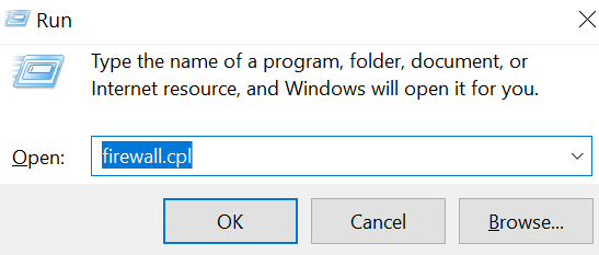
In the Search Command Prompt field of your desktop, type Run. The Run window opens.

-
In the Open field, type firewall.cpl, and then click OK. The Windows Defender Firewall window opens.
-
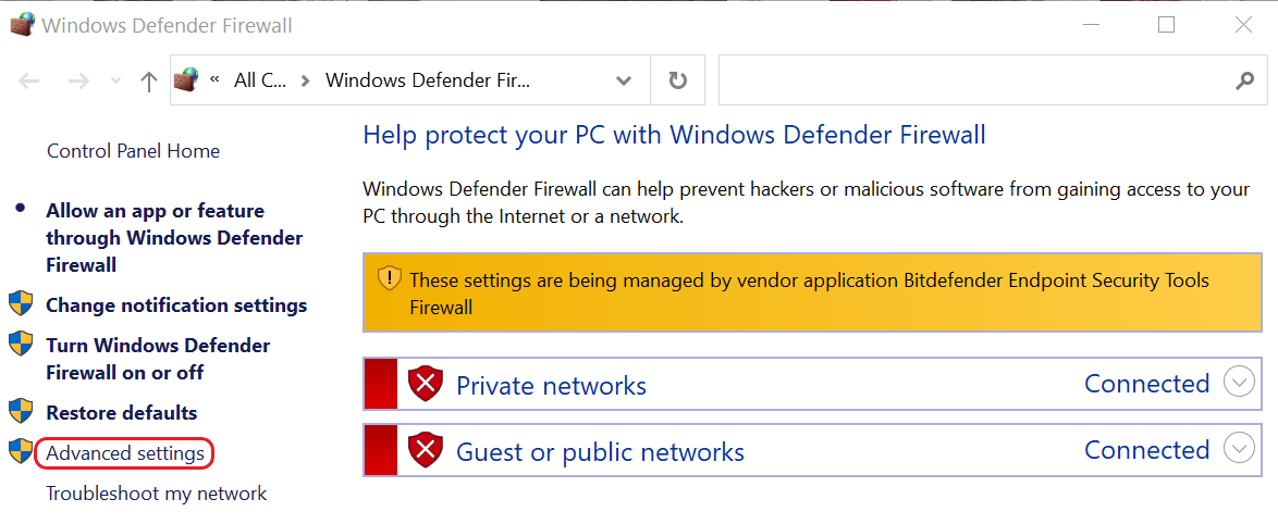
In the left pane, click Advanced Settings. The Windows Defender Firewall with Advanced Security window opens.
-
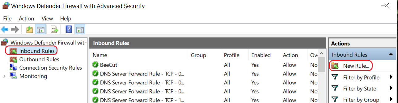
In the left pane, click Inbound Rules. In the Actions pane, click New Rule...
5. In the Rule Type window, select Port, and then click Next.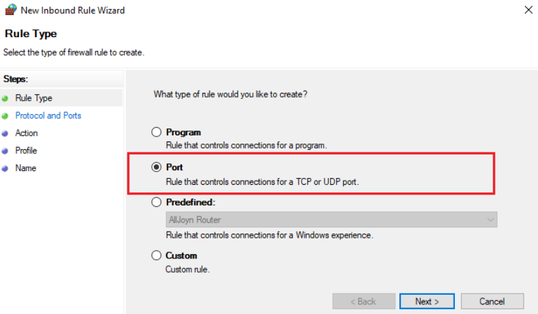
6. In the Protocol and Ports window, select TCP and Specific local ports. Type in 8883 in the adjacent field. Click Next. 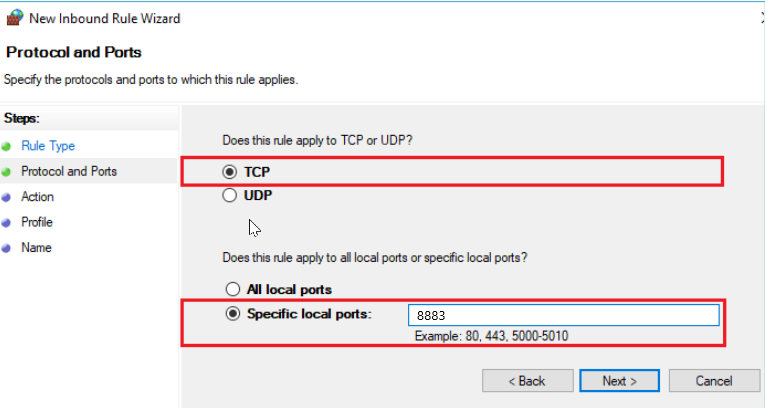
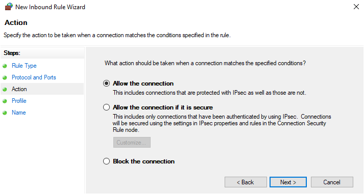
7. In the Action window, do the following steps:
a. In the right pane, click Action, select Allow the connection, and then click Next.
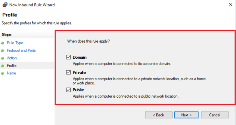
b. In the right pane, click Profile, select all three check boxes, and then click Next.
c. In the right pane, click Name, and then type in a name for your MQTT port rule. For example, you might type in MQTT Service Port. Click Finish.
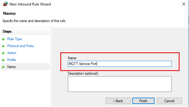
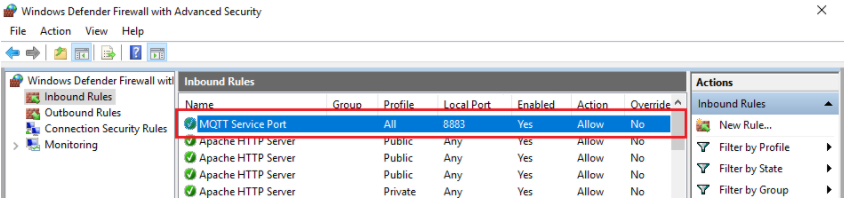
The new MQTT port rule is now listed in the Inbound Rules area of Windows Defender Firewall with Advanced Security window.
templates.json file
The templates.json file maps the devices, channel type, and channel number to a unique DNP3 input type and index number.
The templates.json file has the following sections:
- The DefaultVariations section defines the DNP3 variations for BinaryInput, AnalogInput, and Counter that are used for static and event data
Static data refers to a point’s current or most recently recorded value. For BinaryInput, “static data” refers to the present on/off condition. For AnalogInput, static data contains the value of an analog measurement at the instant it is transmitted. Static data is pulled from the outstation and has no timestamp.
Event data is associated with changes in points, such as state changes, measurement at some threshold, or an analog input leaving its defined threshold range. Event data is pushed by the outstation as an unsolicited response and does include a timestamp.
Variations are different formats for data types in a group. Each group has a set of variations. The following table shows what group numbers, variations, and data types are in each input type.
|
Input Type |
Group Number (Type) |
Variations |
|
BinaryInput |
1 (static) |
1: Package format having single bit binary input state without status flag. 2: Each DNP3 point is returned with a single byte having status flags indicating the point status (such as online/offline, lost communication, over range, and so forth). |
|
2 (event) |
1: One byte for reporting state of input and status flags without time. 2: One byte for reporting state of input and status flags with absolute time when event occurred. 3: One byte for reporting state of input and status flags with relative time when event occurred. Group 51 establishes the basis for relative time. |
|
|
AnalogInput |
30 (static) |
1: 32-bit integer with flag 2: 16-bit integer with flag 3: 32-bit integer 4: 16-bit integer 5: 32-bit float with flag 6: 64-bit float with flag |
|
32 (event) |
1: 32-bit integer with flag 2: 16-bit integer with flag 3: 32-bit integer with flag and event time* 4: 16-bit integer with flag and event time * 5: 32-bit float with flag 6: 64-bit float with flag 7: 32-bit float with flag and event time * 8: 64-bit float with flat and event time * |
|
|
Counter |
20 (static) |
1: 32-bit integer with flag 2: 16-bit integer with flag 5: 32-bit integer 6: 16-bit integer |
|
22 (event) |
1: 32-bit integer with flag 2: 16-bit integer with flag 3: 32-bit integer with flag, delta** 4: 16-bit integer with flag, delta** 5: 32-bit integer with flag and event time * 6: 16-bit integer with flag and event time * 7: 32-bit integer with flag and event time *, delta** 8: 16-bit integer with flag and event time *, delta** |
* Time of the data sample or the local timestamp of the SCADA server.
** The absolute value of the difference between the last reported value and the current value.
- The AnalogInputs, BinaryInputs, and Counter sections map the device's channel type to a specific DNP3 input type. The channels of each device are mapped to a specific DNP3 index, based on the device's channel type. Each DNP3 input type section contains the following information to map all channels of each device :
- Source - Defines a device's channel type and channel number.
- Active - By default, Active=true to include the Source in the templates.json file. If Active=false, the Source is not included in the mapping file.
Tip: If you need to exclude unneeded or unwanted Sources, add the line "Active":false. Alternatively, create a different templates.json file that has only the Sources that are actually used.
- Destination - Defines an index and class for DNP3 based on the defined Source properties.
- Index is a sequential number that gives each Source a unique identifier.
- Class is a way to organize your data for optimized DNP3 polling because the response polling messages are small and efficient. The value of Class can be 1-3.
Typically, all devices are assigned to Class1, but you can group your devices according to polling frequency needs. For example, if you configure your SCADA to poll specific devices every 10 seconds, you can assign these devices to Class1. If the SCADA polls other devices every 10 minutes, you can assign those devices to Class2.
Example of AnalogInputs
In this example, data coming from a serial sensor on channel 0 will be mapped to AnalogInputs and Index= 0. Data coming from an analog type on channel 0 will be mapped to AnalogInputs and Index=1.
"AnalogInputs": [
      {
        "Source": {
          "ChannelType": "Serial",
          "ChannelNumber": 0
        },
        "Destination": {
          "Index": 0,
          "Class": "Class1"
        }
      }
{
        "Source": {
          "ChannelType": "Analog",
          "ChannelNumber": 0
        },
        "Destination": {
          "Index": 1,
          "Class": "Class1"
        }
      }
]
Example of BinaryInputs
In this example, data coming from a VBAT (external power voltage) technical stream on channel 2 will be mapped to BinaryInputs, Type=Power, and Index=0.
The next data is from the TEMP technical stream. This stream has two channels:
-
-
Channel 0 is for temperature. It will be mapped to BinaryInputs, Type= TemperatureHumidity, and Index=1.
-
Channel 1 is for internal humidity. It will be mapped to BinaryInputs, Type= TemperatureHumidity, and Index=2.
-
"BinaryInputs": [
      {
        "Source": {
          "ChannelType": "Power",
          "ChannelNumber": 2
        },
        "Destination": {
          "Index": 0,
          "Class": "Class1"
        }
      }
{
        "Source": {
          "ChannelType": "TemperatureHumidity",
          "ChannelNumber": 0
        },
        "Destination": {
          "Index": 1,
          "Class": "Class1"
        }
      }
{
        "Source": {
          "ChannelType": "TemperatureHumidity",
          "ChannelNumber": 1
        },
        "Destination": {
          "Index": 2,
          "Class": "Class1"
        }
      }
]
In the default templates.json file supplied by Ayyeka, the inputs are configured according to common use. It is recommended to make the value of Destination:Index sequential according to the input type (AnalogInputs, BinaryInputs, and Counter).
The following table lists the mapped ChannelType name, ChannelNumber range, Index range, and Class that you can use in the default templates.json file.
|
InputType |
Source: ChannelType |
Source:ChannelNumber |
Destination:Index (*) |
Destination:Class |
|
Counters |
PulseCounter |
0 – 5 |
0 – 5 |
Class1 |
|
BinaryInputs |
Digital |
0 – 5 |
0 – 5 |
Class1 |
|
AnalogInputs |
Serial |
0 - 49 |
0-49 |
Class1 |
|
AnalogInputs |
Analog |
0 - 3 |
50-53 |
Class1 |
|
AnalogInputs |
Power |
0 - 9 |
54 - 63 |
Class1 |
|
AnalogInputs |
TemperatureHumidity |
0 - 9 |
64 - 73 |
Class1 |
|
AnalogInputs |
CellularSignal |
0 - 9 |
74 - 83 |
Class1 |
You may create your own customized template to meet your needs. You can have multiple templates in order to group devices according to their function. Each user-defined template is added to the default templates.json file.
Every device must be assigned to a template. Otherwise, the device’s data will be discarded.
mappings.json file
Every outstation must have a mapping file assigned to it. The file configures each device that is assigned to that outstation to use a specific template. The file also defines an offset for each device to distinguish the channels of each device from the channels of the other devices in the outstation.
By default, one outstation is defined in the appsettings file. The default mappings file associated with the default outstation is mappings.json. A maximum of 650 devices may be assigned to an outstation. Therefore, if you have more than 650 devices, additional outstations must be defined in the appsettings.json file. Each outstation must have a unique mappings file.
Example:
The following code snippet is from an example file, mappings_outstation1.json, for an outstation called Outstation1.
Outstation1 has two devices assigned to it, and they both use the same template, DefaultTemplate, defined in the templates.json file.
Note that the devices have a unique offset to differentiate their channels.
[
  {
    "AKID": "24A04F085C80A4B0",
    "TemplateName": "DefaultTemplate",
    "Offset": 0
  },
  {
    "AKID": "24A04F085C80A9D0",
    "TemplateName": "DefaultTemplate",
    "Offset": 100
  }
]
By using the template.json file with the mappings file, we can determine a unique Index for each channel per device per outstation.
In the above example, we see the following information:
|
AKID |
Offset |
Index Range |
True Index Range |
|
24A04F085C80A4B0 |
0 |
0 - 99 |
0 - 99 |
|
24A04F085C80A9D0 |
100 |
0 - 99 |
100 - 199 |
metadata.json file
You can define custom attributes in order to add descriptive information about the devices and their channels. These custom attributes can be used in your CSV output files or in the OPC-UA data.
In CSV, you can later filter data based on custom attribute values. Alternatively, you can set CustomAttributesOutputNoData=false to exclude it from the output file.
- Open the metadata.json file with a text editor, and then do the following steps:
-
In the CustomAttributes area, define as many attributes for devices and channels as needed.
-
-
-
-
In the DeviceCustomAttributes area, define as many Attributes as you need to describe the device. For example: name, serial.number, location, installer, address, account.
-
In the ChannelCustomAttributes area, define as many Attributes as you need for channels. For example: name, units, sensor.name, minimum, maximum.
-
-
b. In the DeviceMapping area, add each device with its channels, AKID, and Attributes.
The device attributes must be the same that you defined in the DeviceCustomAttributes area in the previous step.
Example:
Let’s say that you have device AKID= 2021017740 with two serial channels, one for pressure and one for temperature.
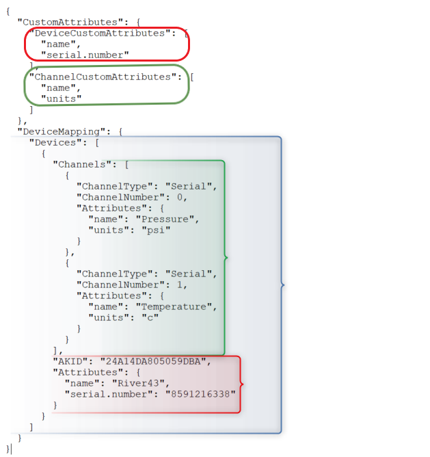
Note that the Channels section (in green) has two attributes, “name” and “units”, that you defined in ChannelCustomAttributes. These attributes are applied to the two serial channels.
Likewise, the Attributes section (in red) has two attributes, “name” and “serial.number”, that you defined in DeviceCustomAttributes. These attributes are applied to the device with AKID= 24A14DA825059DBA.
In both Devices and Channels, you do not need to provide values for all Attributes for every device and channel.
2. Open the appsettings.json file, and then go to either the CSV or the OPC-UA sections:
In the “Header” and “Line” rows, change the original lines to use the appropriate device and channel custom attributes that you defined in the metadata.json file.
Change the default “Header” and “Line” rows from:
"Header": "AKID,ChannelType,ChannelNumber, TimeStamp,Value",

"Line": ",,,,",
to:
"Header": "Serial Number, Channel Name, Channel Number, Sampling Time, Value, Units",

"Line": ",,,,,",
- We remove the “AKID” and replacing it with the device custom attribute “Serial Number”, which makes it easier to identify each device.
- We also replaced “ChannelType” with the user-friendly custom attribute “Channel Name”.
- We added the channel custom attribute “Units” so that Value is clearer to understand.
Stopping, Starting, and Uninstalling Agent
The Agent is a standard Microsoft Windows service.
To stop the Agent:
-
In your desktop, open Windows Services.
-
In the Services list, right-click FAI.Agent, and then click Stop.
To start the Agent:
-
In your desktop, open Windows Services.
-
In the Services list, right-click FAI.Agent, and then click Start.
The Agent is launched. The default location of the log file is what you defined in Serilog section of your MQTT Broker configuration file.
To uninstall the Agent:
-
In the Search box in the desktop, type Settings.
-
In the Settings window, click Apps.
-
Scroll down to FAI.Light, and then click its icon. Click Uninstall.
Information about Popular MQTT Brokers
Comparison of MQTT Brokers - Comparison of the seven most popular MQTT Brokers.
RabbitMQ - Overview, installation, tutorials, CLI tools, configuration, authentication, networking, messages, queues, and other features.
Mosquitto - Overview, configuration file, command line interface
HiveMQ – Introduction, installation, getting started, security, monitoring, logging, and troubleshooting.
Appendix B
CSV parameters in apsettings.json
| Parameter | Description | Default Value |
|
Format section |
|
|
|
Header |
Specifies from 0 to many lines of text that appear at the top of each CSV file. Typically, there is a single row with column headings, separated by commas, for each data item in the data rows (referred to as "Line" below). You can add a second header line by inserting \n. For example, the default "Header” is: "Data\nAKID,ChannelType,ChannelNumber,TimeStamp,Value" “Data” is the first header line. The second header line is “AKID, ChannelType, ChannelNumber, TimeStamp, Value”. |
“Header”: "Data\nAKID,ChannelType,ChannelNumber,TimeStamp,Value" |
|
Line |
Each row, listing samples’ attributes separated by commas, corresponds to a single polled sample. It defines which values that are associated with the sample should appear in the CSV file. Each attribute in ““ is replaced with the actual value. For example, will be replaced with the channel’s actual number. report.id is sent with every transmission session. All topics that are transmitted in a single transmission are put into a report. channel.type can be Serial, Analog, Digital, Power, PulseCounter, TemperatureHumidity, CellularSignal, and GPS. sample.datetime is the datetime stamp from the device that the sample was taken. |
device.akid, report.id, channel.type, channel.type.raw, channel.number, sample.datetime, sample.value |
| CustomAttributesOutputNoData | All custom attributes for the device and the channels will be included in the output file, even if the custom attribute has no data. | true |
| CustomAttributesNoDataValue | If a custom attribute for a device has no data, export the string that you type in. For example, you might use "NA", without quotation ("") marks, to indicate that the custom attribute has no data. | |
|
DateTime |
Specifies the format of the sample.datetime attribute in the Line parameter above. You can use any datetime format that complies with ISO 8601 standard.
|
MM/dd/yy HH:mm:ss Where:
|
|
TimeZone |
Specifies the international time zone to which all timestamps are converted. |
Local |
|
Partition section |
|
|
|
SplitBy |
If you want to partition sample data into separate CSV files, you can tailor how the data is split up to the output file(s). You can split the data into separate output files by AKID, channel type, channel number, and other attributes. You can split the data by several attributes. For example, you might want to split the data first by AKID, and then split that data by channel type. Example of double split: “_” |
device.akid
|
|
Output section |
|
|
|
Dir |
Specifies the directory in which the CSV files should be placed. If the directory path does not exist, it will be created. |
C:\\FAIAgentCSV Note the double backslashes (\\). |
|
DateTime |
The date and time of when the CSV file was created. The DateTime value is the time on the computer where the CSV files are created. The value replaces the attribute in the FileName parameter below. |
MM-dd-yy__HH-mm-ss Where:
Note the double underscores (__) between “yy” and “HH”. |
|
FileName |
The CSV files will be named according to what you defined here. You can name the file with any free text. You may add the two attributes, and of the Output section, in the name. Example: You define the FileName as test__.csv. You’ve accepted the default values for and . The exported file name will be test_24A14DA805059DBA _05-01-21__12-23-33. |
export__.csv |
|
Filters section (optional) |
|
|
|
|
It is recommended to add the optional “Filters” section so you can include only the Raw Value data that you want. Alternatively, filters can exclude what you do not want. You can filter by any attribute. Each rule is defined by applying a regular expression to the value of a sample’s attribute. Note:
For details about what filter options you can use in Regex, see RegexOne. See the following examples for syntax of Var and Regex. Examples:
"Var": "channel.type", "Regex": "Serial|Analog|Digital|PulseCounter"
"Var": "sample.value", "Regex": "[\d]{2}(.+?)" |
DNP3 parameters in appsettings.json
|
Parameter |
Description |
Default Value |
|
Active |
The Agent is enabled. |
false |
|
NumCoreThreads |
The number of threads that handle all requests to the DNP3 master. The threads run in the background. Recommended: The value should be the same as the number of CPU cores in the machine that is running the Agent. |
4 |
|
Templates |
Maps the devices, channel type, and channel number to a unique DNP3 input type and index number:
The default template.json file that is provided supports the typical configuration suitable for most sites. It accomodates all current configurations and includes options for future expansion. For details about the template.json file, see templates.json file in the Appendix. |
./templates.json |
| AutoMapDevicesToTemplate section | ||
| Active |
If set to true, then when a new device transmission is received, the device is added to the mapping file (by default: mappings.json) of the outstation that you defined below. Note: You must restart the Agent to activate the automapping feature.
If set to false, all the other parameters in this section are ignored. You must manually add new devices to mapping files. |
false |
| Template |
If Active=true, each device that is assigned to the outstation that you defined below uses this template. If Active=false, this parameter is ignored. |
DefaultTemplate |
| Offset |
If Active=true, the offset for each device distinguishes the channels of each device from the channels of the other devices in the outstation. If Active=false, this parameter is ignored. |
100 |
| Outstation |
If Active=true, new devices will automatically be assigned to this outstation. If Active=false, this parameter is ignored. |
Outstation1 |
| MappingBackupLocation |
If Active=true, the original mappings.json file is backed up to this file before it is updated. The backup file is overwritten each time. If Active=false, this parameter is ignored. |
./mappings_backup.json |
More DNP3 parameters in appsettings.json
|
Parameter |
Description |
Default Value |
|
Name |
The name of the outstation. This name will be displayed in the log files (for details, see the Serilog section below). |
test |
|
Address |
The IP address of the SCADA and the communication port for both the SCADA and the Agent. 0.0.0.0:20000 means that the Agent listens to all IP addresses on port 20000. |
0.0.0.0:20000 |
|
Outstation Address |
This number identifies the outstation to the SCADA master. Each outstation must have a unique number. |
|
|
Master Address |
The SCADA ID number. Each SCADA in the network must have a unique ID number. |
|
|
LinkErrorMode |
Recommended: Do not change the default value unless you have expertise in DNP3. |
Close |
|
Logging |
||
|
ApplicationDecodeLevel |
Recommended: Do not change the default value unless you have expertise in DNP3. |
"ObjectValues" |
|
TransportDecodeLevel |
“Nothing” |
|
|
LinkDecodeLevel |
“Nothing” |
|
|
PhysDecodeLevel |
“Nothing” |
|
|
EventBuffers |
|
true |
|
MaxBinary |
Recommended: Do not change the default value unless you have expertise in DNP3. |
10000 |
|
MaxCounter |
10000 |
|
|
MaxAnalog |
10000 |
|
|
EnableUnsolicited |
Report event data to the SCADA regardless of the SCADA’s polling cycles. |
true |
|
Details |
||
|
SolicitedBufferSize |
Recommended: Do not change the default value unless you have expertise in DNP3. |
2048 |
|
UnsolicitedBufferSize |
2048 |
|
|
RxBufferSize |
2048 |
|
|
ConfirmTimeoutMs |
5000 |
|
|
MaxUnsolicitedRetries |
4294967295 |
|
|
UnsolicitedRetryDelayMs |
100 |
|
|
KeepAliveTimeoutMs |
60000 |
|
|
SupportBroadcast |
true |
|
|
Mappings |
||
|
Mappings |
The mappings file lists all devices in the specified outstation that will deliver data to the SCADA. In addition, the mappings file designates which template file is associated with each device. The Offset enables each device to have a unique range of DNP3 indices. The file contains the following JSON properties for each device in the outstation:
This offset is added to each channel's index number (as defined in the associated template) for each device, to define the true index number. As a result, the offset makes each channel's true index number unique within the outstation. Recommended: Do not change the default values unless you have expertise in DNP3. For details, see mappings.json file and templates.json file in the Appendix. |
|
MQTT section in appsettings.json
|
Parameter |
Description |
Default Value |
|
ClientID |
Identifies each Agent that connects to an MQTT Broker. This ID must be unique for each Agent and Broker. The ID must be 1-23 characters. |
|
|
BrokerAddress |
The IP or DNS name of the MQTT Broker at your site. |
localhost Note: Do not include the prefix "https://" |
|
Port |
Port number on the MQTT server that the Agent must communicate with. |
8883 |
|
UseTLS |
Use TLS security protocol in communication with the MQTT Broker. |
true |
|
AllowUntrustedCertificates,
IgnoreCertificateChainErrors,
IgnoreCertificateRevocationErrors |
Certificates that are signed by a Certification Authority (CA) are used to create a secure connection between the Agent and the MQTT Broker. Note: Untrusted certificates, a chain of certificates where at least one is untrusted, or certificates that have been revoked by their CA might expose the MQTT Broker to security risks. |
false |
|
Username/ Password |
Username and password that are defined on the MQTT Broker. |
guest/guest |
|
SubscribeQos |
The level of QoS (Quality of Service) guarantee between the Agent and the MQTT Broker. The valid levels are: 0 - At most once. Level 0 guarantees a best-effort delivery. There is no guarantee of delivery. 1 - At least once. Level 1 guarantees that a message is delivered at least one time to the receiver. It is possible for a message to be sent or delivered multiple times. 2 - Exactly once. Level 2 guarantees that each message is received only once by the intended recipients. QoS 2 is the safest and slowest QoS level. The device always transmits to the MQTT Broker with QoS =1. This level is not configurable. |
1 |
| CleanSession |
Persistent sessions save all information that is relevant for the client on the MQTT Broker.
|
false |
|
Topics |
The topics that the Agent will subscribe to on the MQTT Broker. A plus sign (+) will replace one topic level. A hash sign (#) will replace several levels and may be used only at the end of an expression. For details about MQTT syntax, see MQTT Topics and Best Practices. Examples:
|
wv/#
|
Details of every Logs level:
Debug Level: This level provides a detailed account of the agent's actions, including all other levels of information. It essentially offers a thorough, step-by-step view of the agent's operations.
Information Level: At this level, you receive details about connections with the broker and the reception of data from it, this level also shows Warnings, Error and Fatal levels logs
Warning Level: Instances of disconnection from the broker or abrupt halts in the agent's operation are highlighted by this level, which also includes Error and Fatal level logs
Error Level: This level is dedicated to identifying and communicating errors that hinder the broker's ability to execute actions. At this level, Fatal level logs are also displayed.
Fatal Level: Reserved for instances where critical errors occur during the initialization o functioning of the agent, this level signifies a severe disruption that renders the agent incapable of functioning correctly.
Please be aware that logs are subject to changes in every new release.
Serilog area in appsettings.json
|
Parameter |
Description |
Default Value |
|
MinimumLevel |
The level of logging information and above that will be written to the log files. Values include Debug, Information, Warning, Error and Fatal. Note: The value is case-sensitive. |
Information |
|
path |
Specifies the directory and file name of the log files. The datetime stamp of the log file creation is appended to the file name. If the directory or file does not exist, it will be created. |
C:/FAILiteLogs/log.txt |
|
rollingInterval |
How often the current log file is closed, and a new file is created. Values include Hour, Day, Month. Note: The value is case-sensitive. |
Hour |
StoreDumps area in appsettings.json
|
Parameter |
Description |
Default Value |
|
Active |
The Agent creates dump files for later use. |
false |
|
Location |
Specifies the directory where the dump files, as defined in StoreBy below, should be written. |
C:\\FAIAgentDumps Note the double backslashes (\\). |
|
StoreBy |
Folder names are by Date, Device, or Both. The following subdirectories are created under the value of Location parameter above:
Note: The value is case-sensitive. |
Date
|
| ArchiveTime | The time interval, in hours, that all dump files will be archived into a zip file. The zip file is located in the directory that you defined in Location above. | 24 |
| RemoveTime | The time interval, in hours, that all zip files will be removed. | 168 |
| MaxSize | The maximum size, in megabytes, of the dump file before it is automatically deleted. | 100 |
Metadata parameters for CSV and OPC UA
|
Parameter |
Description |
Default Value |
|
MatadataLocation |
Location of the metadata.json file. For details, see metadata.json in the Appendix. |
./metadata.json |
|
MatadataBackupLocation |
The original metadata.json file is backed up to this file before it is updated (as defined in UpdateFromIncomingTraffic section below). The backup file is overwritten each time. |
./metadata_backup.json |
|
UpdateFromIncomingTraffic |
||
|
Active |
Updates metadata.json file with incoming information about new devices and new channels per device. Attributes section for each new device and new channel is initially empty. Fill in the Attributes section for each new device and channel. |
false |
|
UpdateInterval |
The interval, in milliseconds, that the metadata.json file will be updated. |
60000 |