An Ultrasonic and Radar Level sensor will not be effective for water streams with foam. Contact Ayyeka for further information, and use either a submersible hydrostatic level sensor or radar level sensor.
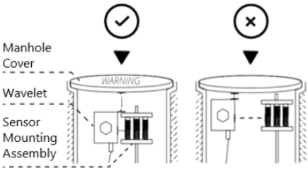
Proper mounting of the sensor is critical. Interference from walls and other obstructions as well as interference from foam and turbulence will cause erratic readings.
Contents
Prerequisites for Mounting
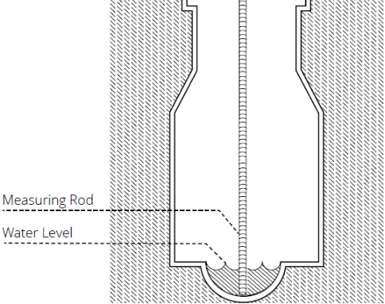
- The minimum manhole depth is 1.2 meters (4 feet). Determine height of the manhole shaft from elevation drawings, or the water level with a rigid measurement rod. When inserted into the shaft, the rod should reach the sewer floor so that the water level can be determined.
- You must know what the range of the sensor is so that you don't mount the sensor too high. You must also know the beam pattern (the number of degrees off the axis beam). Both values are found in the sensor's datasheet.
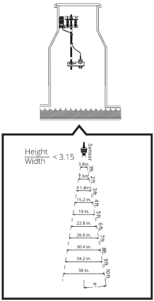
- There is a minimum width of the water stream based on the corresponding height from the face of the sensor to the surface of the stream, per the following diagram. The height (inches):width (inches) ratio must be less than 3.15. If the ratio is more than 3.15, then the sensor must either be moved closer to the water surface, or use an alternative level sensor such as a submersible hydrostatic level sensor or radar level sensor.
-
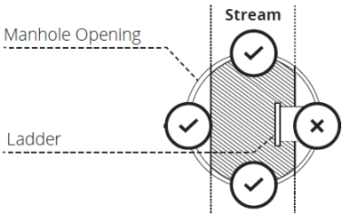
You must have a proper location for mounting. Mounting hardware must be installed in-line with the water stream. Be sure the mounting hardware does not interfere with ascending and descending the ladder.
- To avoid damage to the device when removing the manhole cover, place the top of the mounting bracket a few inches below the cover. You must not install the device too close to the collar of the manhole cover so that when the cover is removed, the device is not damaged. It is recommended to put a label on the outside surface of the manhole cover that warns of sensitive electrical equipment inside.
Installation
- Choose the proper installation location based on the mounting prerequisites.
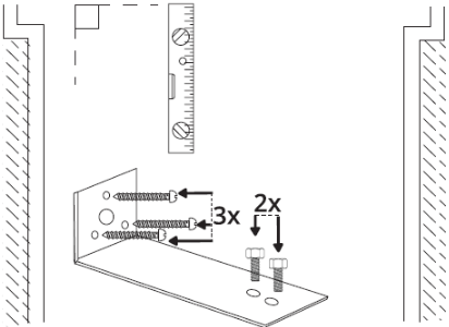
- Loosely thread the two ⁵⁄16”-⁷⁄8” hex bolts into the wall mounting plate. Then, install the wall mounting plate with three screws and ensure it is level vertically.
- Use the provided hex couplers to assemble the rod sections. Each of the four rod sections are 23 cm (9 in.) in length and can be assembled to fit the custom application in lengths up to 1 m (3 ft).
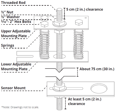
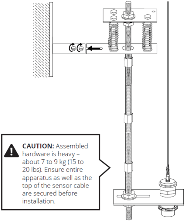
- Prepare the threaded rod according to the following assembly diagram.
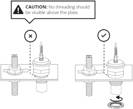
- Place the sensor into the large hole in the sensor mount. Screw on the female threaded coupler to the sensor on the underside of the sensor mount.
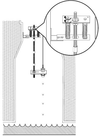
- Carefully lift the entire assembled apparatus and slide the slot of the lower adjustable mounting plate onto the loose bolts of the secured wall mounting plate. Tighten the two bolts of the wall mounting plate.
- The sensor must point down directly to the water surface. Calibrate the x and y-axis by adjusting the bolts on the top of the upper adjustable mounting plate. Use the level to shift the rod angle as needed, and secure it back into place.
Measuring the Water Level
When looking at the readings, you can see how the water level rises and falls relative to the sensor’s fixed location. In the following figure, the distance from the sensor to the top of the water (B) and the height of the water itself (C) are shown. The sum of the two distances gives you the distance of the sensor to the bottom of the water: B + C = A.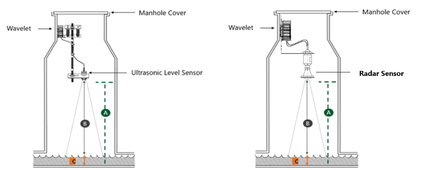
To measure the water level:
1. Find the value of B - get the distance from the sensor face to the top of the water.
a. In the left pane, click Devices, and then click the site whose device you want to use.
b. In the site, click the device that you want to measure.
c. In the device, click Level, and then click the Samples tab to open the table of sample values.
The value of B is in the Raw Value Raw values are in millimeters. In this example, the value of B is 2151 mm at 25-02-2019,11:19.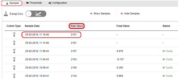
2. Find the value of C – Manually measure the depth of the water. Take two to three measurements every five minutes. Write down the time and the depth. In this example, let’s say that we measured the water depth to be six inches at 25-02-2019,11:19. Then, C= 6 inches.
3. Compute the value of A – Add the values of B + C.
Use the Raw Value (B) at the Sample Date 25-02-2019,11:19 because you have a manual measurement of water depth C at the same time. In this example, B=2151 millimeters.
Since the value of B is in millimeters, we’ll convert it to inches before we can get the sum for A:
B = 2151 mm/25.4 (Convert from millimeters to inches)
= 84.685 inches
A = B + C (Total distance from face of sensor to the bottom of the water)
= 84.685 + 6
= 90.685 inches
4. Configure the Engineering Units Converter.
a. In the right pane, click the Configuration & Thresholds tab to open the Data Processing pane.
b. Click the formula text box for Convert to Engineering Units to open the Conversion window.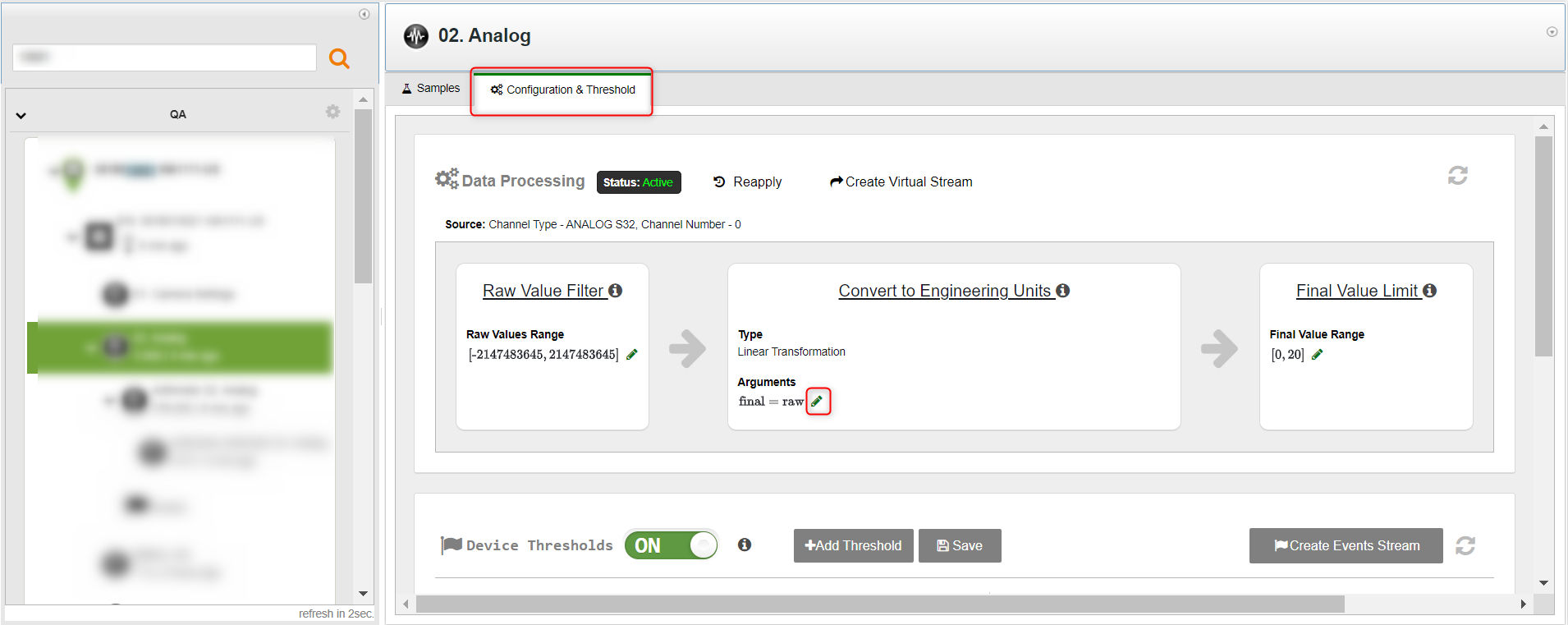
c. In the Conversion window, click  to input the conversion formula.
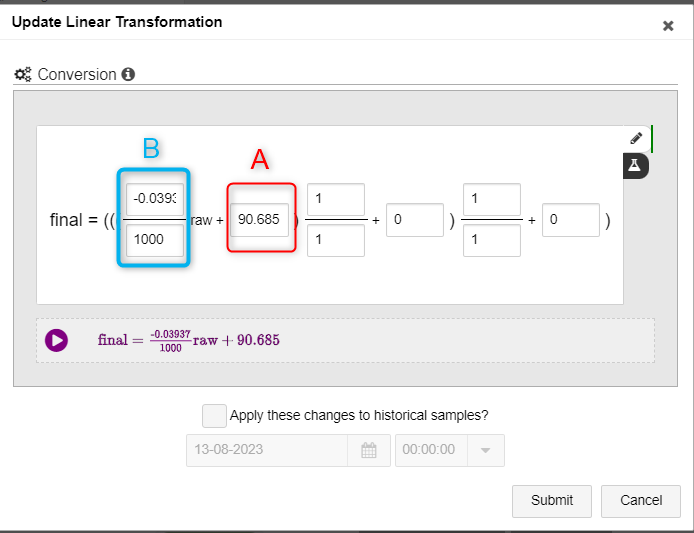
d. To convert the Raw Value (B) from millimeters to inches, the conversion factor is -0.03937/1000 meters. You must include the minus sign (-) in the dividend.
e. Optionally, to update samples that are up to four weeks old with the new formula, click the Update old samples check box. You can update samples up to four weeks back. If you need to update samples older than four weeks, contact Support.
f. Click Submit. The water depth in inches, C, is computed for each sampling and is shown in the Final Value column in the Samples tab.
If you choose to update old samples, wait about 15 minutes for values in Final Value to be updated.
Example: The above example using the metric system
B = 2151 mm (Raw Value from sensor readings)
C = 152.4 mm (Manually measured water level. In our example, 6 inches.)
A = B + C (Total distance from face of sensor to the bottom of the water)
= 2151 + 152.4
= 2303.4 mm
In the Conversion window, you would use the following values: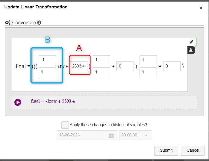
The formula above gives the water depth in millimeters.
- If you want the depth in centimeters, change -1/1 to -1/10.
- If you want the depth in meters, change -1/1 to -1/1000.
Example: Converting distance to level for the analog Vega Radar Sensor
Prerequisites: Vega C11 sensor, with the transformation:
4 mA = 315 inch
20 mA = 0 inch
B = 11.520 mA (Raw Value from sensor readings. In our example = 167")
C = 88.8" (Manually measured water level)
A = B + C (Total distance from the face of the sensor to the bottom of the channel)
= 167" + 88.8"
= 255.8"
In the Conversion window, you would use the following values:
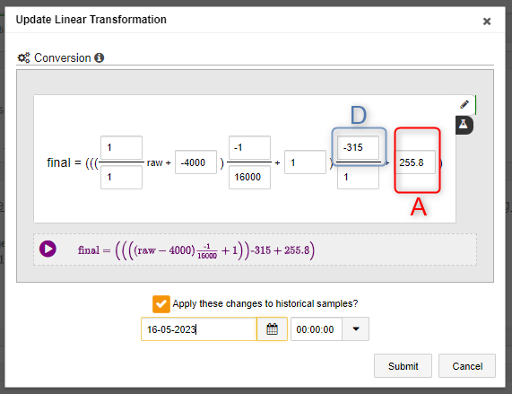
"A" - Total distance from the face of the sensor to the bottom of the channel
"D" - the span of the sensor MAX value and MIN value
D = MAX - MIN =
0" - 315" =
-315"
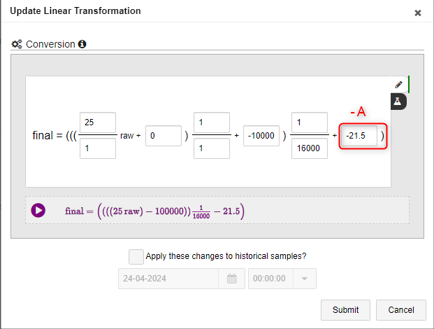
Example: Converting distance to level for the analog Radar/Ultrasonic Sensor
Prerequisites: APG LPU-2428 sensor, with the transformation:
4 mA = 0 ft
20 mA = 25 ft
B = 14.669 mA (Raw Value from sensor readings. In our example = 16.67 ft)
C = 4.83 ft (Manually measured water level)
A = B + C (Total distance from the face of the sensor to the bottom of the channel)
= 16.67 + 4.83
= 21.5 ft
Setting up the transformation formula:
Step 1. Set up and Submit Radar/ultrasonic linear transformation:
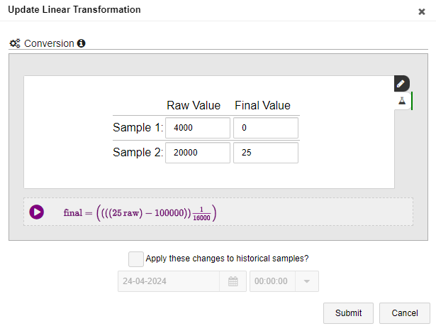
Adjust additional offset: