Table of Contents
LED Status Indications for Wavelet 4R
Accessing the Interface Board LEDs
Viewing the Indicator LEDs
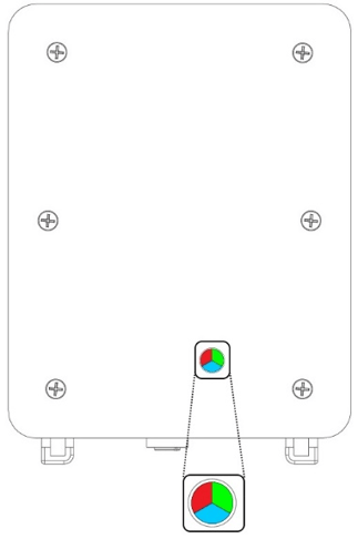
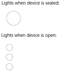
In the device, a round window on the back enables you to see the three indicator LEDs (green, red, and blue). View the LED status through that window.
If you have an early version of a Wavelet 3™ or Wavelet 4™ device that has no window, you need to open the enclosure (as described in Accessing the Interface Board LEDs) to view LED indications.
 |
 |
|
Location of round window – Wavelet sealed |
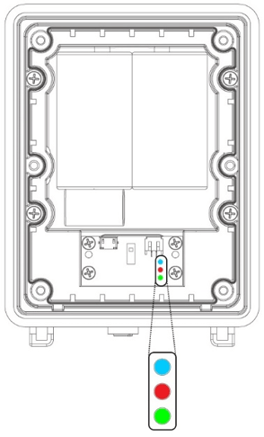
Location of LEDs – Wavelet opened |
 |
 |
|
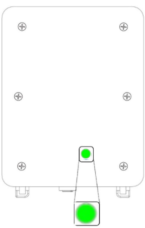
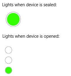
Location of round window – Wavelet 4R sealed |
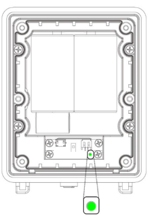
Location of LEDs – Wavelet 4R opened |
LED Status Indications for Wavelet 4R
The following table lists the LED light status for devices manufactured after October, 2021.
|
Green LED Status |
Interpretation |
|
The LED is off |
Not connected to network. The LED light does not blink when the device is sampling. Note: The device might be powered down (power switch is in the OFF position), in Hibernate mode, or have insufficient battery power. Hibernate mode puts the device into an ultra-low power mode. The device will neither take samples nor transmit data. |
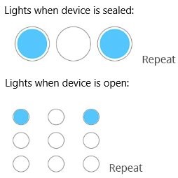
| The LED blinks a long blink followed by a short blink - 3 times | The device is powering up. |
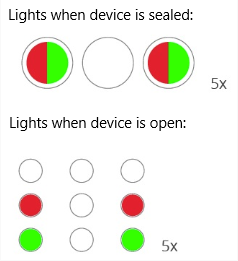
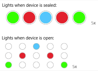
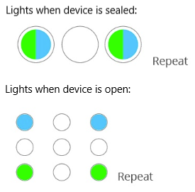
| The LED blinks 4 short blinks - 3 times | Communication error. The device failed to transmit. |
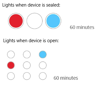
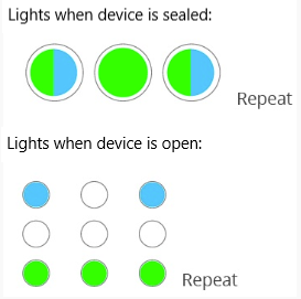
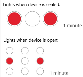
| The LED blinks 3 short blinks - 3 times | The device was just activated by swiping the Magnetic Activator key over the embossed logo on the face of the device. Next, the calibration activity starts, in which the device samples and transmits frequently. |
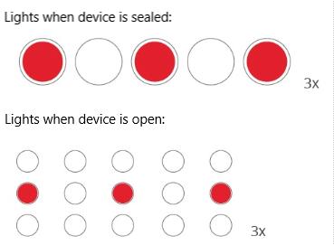
| The LED has 1 long blink - once | Communication is successful. |
LED Status Indications for All Other Devices
|
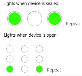
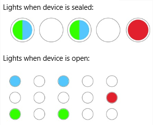
Blue LED remains on |
Transmission of data over LoRa is in progress; the LED will turn off when transmission is complete. |
LoRa-enhanced Wavelet |
 |
|
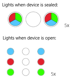
Blue and Red LEDs blink five times |
LoRa communication error. The device failed to transmit. |
LoRa-enhanced Wavelet |
 |
Accessing the Interface Board LEDs
To access the Wavelet's interface board LEDs:
Partially unscrew the six (6) screws located on the back of the Wavelet enclosure, until you can lift off the back panel.
Note: The Wavelet 4R device has only a green LED.
The other devices have three LEDs (COMM, ERROR, and STAT) that are on the interface board, as shown in the figure below. The COMM LED is green, the ERROR LED is red, and the STAT LED is blue.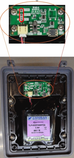
Calibration Mode
Calibration mode is the state of the device during its boot up. While in Calibration mode, no changes are made to the device’s configuration.
A device goes into Calibration mode when you do any of the following actions:
-
The Reboot command is generated by the FAI Pro/FAI Local platform when some commands are sent. Additionally, a “Reboot” command can be sent from the AyyekaGo mobile app.
For example, this command is sent automatically when a device’s configuration is changed.
-
You swipe the magnet over the embossed logo on the front of the device.
For example, you swipe the magnet if you want to force an immediate transmission of sample data rather than wait for the next scheduled transmission.
-
You perform a manual reboot by turning the ON/OFF switch found on the top PCB board of the device to the OFF position, and then later turning it to the ON position.
For example, you turn the ON/OFF switch when changing the device’s desiccants or battery.
Calibration mode affects the following device functions:
-
Transmission – During calibration, the device does not transmit at its regular transmission rate. Instead, the device transmits more frequently (every 1-3 minutes) for the next 10-15 minutes.
-
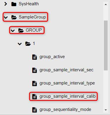
Data Sampling – During calibration, the device does not sample at its regular sampling interval rate (as defined in ADVANCED DEVICE CONFIGURATION > SampleGroup > GROUP > # > group_sample_interval_calib).
-
Bluetooth® - By default, Bluetooth is not enabled in order to conserve the battery. In Calibration mode, Bluetooth is enabled as long as the device is in Calibration mode (10-15 minutes) or as long as the device is connected to the mobile app.