Contents
Advantages and limitations of LoRa-enhanced Wavelet
Viewing LoRa activity and information in the Management UI
Viewing LoRa information in Device view
Viewing LoRa Uplinks in Device Reports
Viewing LoRa command status in Device Commands
Viewing LoRa-transmitted stream samples
Setting LoRa advanced configuration settings
Description of LoRa advanced configuration settings
Calibration Home Interval Seconds
Overview - What is LoRa?
Long Range WAN (LoRaWAN) is a low power Wireless Area Network for long-range bidirectional IoT (Internet of Things) connectivity. LoRa is an open-source, low-bitrate, wireless telecommunications system that utilizes unlicensed bands, transmitting a few bytes of data every few minutes over the LoRaWAN using low power. End-devices use LoRa to communicate with LoRa gateway(s), which are connected to the Internet and which act as transparent bridges to relay messages between these end-devices and a central network server.
Ayyeka supports LoRa-enhanced Wavelet devices. These devices include a hardware extension that provides LoRa connectivity in addition to existing cellular connectivity. Note that LoRa connectivity does not replace regular cellular connectivity: in a LoRa-enhanced Wavelet, all information is transmitted and received over the cellular network as in a regular Wavelet, in addition to LoRa transmissions.
Ayyeka supports LoRa-only Wavelet devices. These devices do not have cellular connectivity. As a result, Support cannot send commands or see any logs if troubleshooting is needed. AyyekaGo mobile app can configure only sampling interval and transmission interval.
Wavelet devices cannot act as a LoRa gateway.
LoRa Uplinks and Downlinks
A transmission from a LoRa-enhanced device to the server is called an Uplink, and transmission back from the sever to the LoRa-enhanced device is called a Downlink.
LoRa Uplink rate
Because LoRa utilizes unlicensed bands, its Uplink transmission rate is limited by local regulations. For example:
- In Europe – The minimum LoRa transmission interval is about 12.5 minutes (roughly five LoRa transmissions per hour)
- In the US – If you perform frequency hopping, there is no restriction. Since the LoRa-enhanced Wavelet enforces the frequency hopping limitation, you can set any LoRa transmission interval you wish for the Wavelet in the US.
LoRa Downlink rate
Local regulations also restrict the maximum number of LoRa downlinks. To comply with local regulations in almost all locales, Ayyeka limits LoRa downlinks to 10 downlinks per day per device.
Advantages and Limitations of LoRa-enhanced Wavelet
LoRa technology advantages
LoRa technology offers the following advantages:
-
Receipt of regular heartbeat messages from the Wavelet
Every LoRa transmission is a signal indicating the Wavelet is alive. This means you receive regular, frequent heartbeat messages from a LoRa-enhanced Wavelet.
-
Receipt of near-real-time sample information
In each LoRa uplink, up to two recent samples (=sensor readings) can be sent with the LoRa signal.
- Ability to initiate near-real-time Wavelet configuration
Every LoRa uplink queries the Server for a downlink (response) from the server. The server utilizes this for Wavelet configuration, as follows: Every time a command (such as a threshold definition) is queued in the server for downloading to the Wavelet, the server also automatically creates a LoRa – Transmit Now command that will automatically be sent in response to the next Uplink received from the Wavelet. When the Wavelet receives a LoRa - Transmit Now response, the Wavelet initiates an unscheduled cellular connection, and a standard communication session is established with the server. In the session:
-
- The Wavelet sends all the information it had stored since the last transmission session (such as sample readings, events, health info, etc.)
- The server sends the Wavelet all the queued commands intended for the Wavelet, such as configuration settings, firmware upgrades, etc.
LoRa technology limitations
LoRa technology has the following limitations:
- The LoRa transmission interval should comply with local regulations. In Europe, for example, this limits the interval to no shorter than 12.5 minutes (=about five LoRa transmissions per hour).
- Ayyeka limits the number of LoRa downlinks to 10 per day per device.
- By the nature of LoRa technology, not every LoRa connection attempt succeeds.
- In each LoRa uplink, up to two samples (=sensor readings) can be sent with the LoRa signal. The LoRa transmission includes the two most recent samples that had not already been sent by LoRa, from two different streams. If the Wavelet is sampling only one stream, only one sample is sent. This means that if the sampling interval is longer than the LoRa transmission interval, there may not be any recent samples to send with some uplinks.
Viewing LoRa Activity and Information in the Management UI
Various LoRa information and activity can be viewed in the Management UI.
Viewing LoRa Information in Device View
To view device-related LoRa information, click Devices in the sidebar.
You can view the following LoRa information:
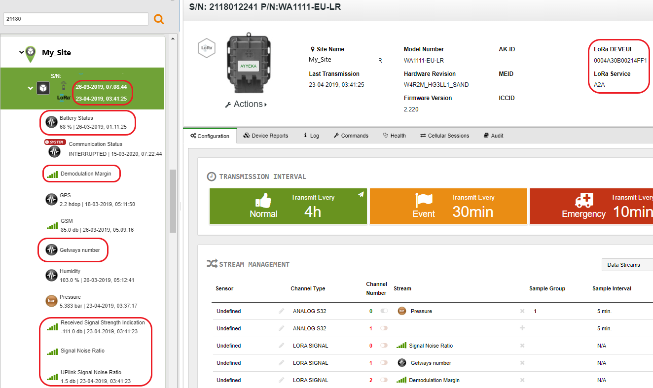
Last transmission time
In the sites tree pane, below the device Serial Number, the TX field indicates when the last transmission occurred – regardless of whether it was a LoRa or a cellular transmission.
Stream information
In the sites tree pane, the following LoRa streams information is displayed. Some of the information originates from the device, and some from the LoRa network.
- The LoRa information originating from the device includes the following. Note that this information (except for Battery Status) is updated for every uplink:
- Battery Status – Battery level notification. This is received in a LoRa uplink twice a day.
- Demodulation Margin – Indicates how many dBm you can lose without losing your LoRa connection
- Gateways number – Displays how many LoRa gateways (antennas) are receiving LoRa transmissions from this device
- Signal Noise Ratio – An indication of LoRa signal quality compared to the background noise
- The LoRa information originating from the LoRa network includes the following. Note that this information is updated for every uplink:
- Received Signal Strength Indication – The LoRa signal quality of the device, as measured by the LoRa network
- Uplink Signal Noise Ratio – An indication of LoRa signal quality compared to the background noise, as measured by the LoRa network
Device information
In the top right pane, the following LoRa information is displayed:
- An icon indicating the device is a LoRa-enhanced device

- DEVEUI – The unique ID of the LoRa hardware extension
- LORA SERVICE – The name of the LoRa service provider
Viewing LoRa Uplinks in Device Reports
To view information about LoRa uplink communication sessions:
- Click Devices in the sidebar, and then click the device name.
- In the right pane, click the Device Reports tab.
The icon in the left-most Comm Type column indicates whether the session was a cellular session  or a LoRa session
  .
.

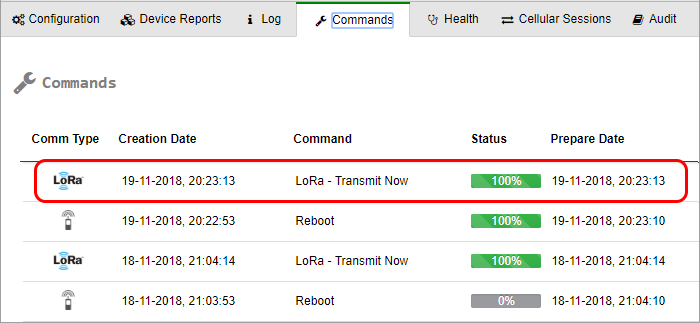
Viewing LoRa Command Status in Device Commands
In a LoRa-enhanced Wavelet, whenever a command (such as a firmware upgrade) is queued in the server for downloading to the Wavelet, the server also automatically creates a LoRa Transmit Now downlink LoRa command. This command is sent in response to the next Uplink received by the server from the Wavelet over LoRaWAN.
To view LoRa commands and their status:
- Click Devices in the sidebar.
- In the Sites Tree pane, click the device name.
- In the right pane, click the Commands tab.
-
- The icon in the left-most Comm Type column indicates whether the command is a cellular command
 or a LoRa command
  .
. - The icon in the Status column indicates the status of the command.
- The icon in the left-most Comm Type column indicates whether the command is a cellular command
By the nature of LoRa technology, not every LoRa connection attempt succeeds; uplink may have failed, or uplink may have succeeded but downlink failed. Therefore, the server’s downlink LoRa – Transmit Now command is defined to be persistent. This means that if no cellular session is established in this LoRa interval, the command is re-sent at the next LoRa interval. After 3 failed send attempts – where failure means that no cellular connection was established in the LoRa interval – the command is marked as failed.
The Status of a LoRa command is a green 100%  when both of the following actions are done:
- The LoRa – Transmit Now command was sent to the Wavelet (a down link occurred)
- A cellular session was established between the Wavelet and the server
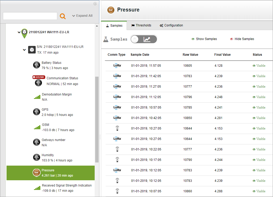
Viewing LoRa-transmitted Stream Samples
For each specific sensor, you can view the sensor samples sent in a LoRa transmission.
To view samples sent in a LoRa transmission:
- Click Devices in the sidebar, and click the stream name in the Sites Tree pane.
- In the right pane, select the Samples tab.
The icon in the left-most Comm Type column indicates whether the sample was sent via a cellular session or a LoRa session
.
Setting LoRa Advanced Configuration Settings
Some advanced configuration tasks can only be done using the Device Advanced Configuration hierarchical tree, available through the UI. One of those tasks is the advanced configuration of LoRa settings in a LoRa-enabled device.
To set advanced LoRa configuration:
- In the UI, click Devices in the left pane.
- In the Sites Tree pane, select the device.
- In the right pane, select the Configuration tab.
- Scroll down past the Stream Management table, and click Advanced Device Configuration.
- In the configuration tree that appears, expand the LPWAN node.
- Define the LoRa settings in the parameter nodes nested under the LPWAN node. The available LoRa settings are described in Description of LoRa Advanced Configuration Settings below. To change the setting of a parameter, such as the Calibration Home Interval Seconds parameter:
- Click the Calibration Home Interval Seconds node.
- Click the current value, appearing in orange on the right.
- Click Set Setting, and in the dialog box that appears, enter the desired LoRa interval in seconds.
Description of LoRa Advanced Configuration Settings
This section describes the available LoRa advanced configuration settings.
Note: Except for the following three parameters, do not change any LoRa advanced parameter settings without consulting with support@ayyeka.com. Nonetheless, we also recommend that even when changing the following three parameters, you consult Support first:
Active
|
Description: |
Defines the LoRa enabled/disabled state of the device. |
|
Options: |
|
Home Interval Seconds
|
Description: |
Defines the LoRa transmission interval, in seconds, which is the time between LoRa transmissions. This value should comply with local regulations. For example, in Europe the minimum transmission interval is about 12.5 minutes. The default value is 900 seconds, which is 15 minutes. |
|
Note: |
In the US, if you perform frequency-hopping, you can transmit using LoRa as frequently as possible. Since the LoRa-enhanced Wavelet enforce the frequency‑hopping limitation, you can set any LoRa transmission interval you wish for the Wavelet in the US. |
Calibration Home Interval Seconds
|
Description: |
Defines the LoRa transmission interval, in seconds, for times when the Wavelet is in calibration mode. Although the LoRa transmission interval should comply with local regulations, it can be set to a higher rate for a limited amount of time. A high LoRa transmission rate is necessary when the Wavelet is in Calibration mode. As soon as the Wavelet exits Calibration mode, the LoRa transmission frequency automatically reverts back to its Home Interval Seconds rate. The default value is 120 seconds, which is 2 minutes. Do not set the value to less than 2 minutes. |
Link Protocol
|
Description: |
Defines the protocol to use for the payload, that is, how to encode the samples sent with the uplink. |
|
Options: |
|
Require acknowledgement
|
Description: |
Defines whether every uplink requires an ack from the server. Although the ack response can also include a LoRa – Transmit Now instruction, requiring an ack severely limits the option of sending a LoRa – Transmit Now instruction. The reason is that the maximum number of downlinks that can be sent per day is 10. If you require acks, then the first 10 uplinks on a given day will trigger a downlink with an ack, after which you will not be able to send any more downlinks until the next day. For this reason, requiring acks should only be set when running diagnostics. |
|
Options: |
|
Retry TX count
|
Description: |
Defines the number of time to re-send an uplink if an ack, although required, was not received. This is relevant only if Require acknowledgement is set to 1 (=ack required). When Retry Tx count is set to a whole number larger than 0, an uplink is re-sent every 30 seconds, until either an ack is received, or the defined number of retry times has been reached. |
|
Options: |
|
Done one-time setup
|
Description: |
Provides an indication of whether initial LoRa setup was performed. |
|
Options: |
|
Enable Events
|
Description: |
This parameter has been deprecated. |
App_key
|
Description: |
Displays the encryption key for this specific DEVEUI (=LoRa hardware component ID) and App_EUI (=LoRa app ID). The App_key encrypts both the uplink and the downlink transmissions. |
App_EUI
|
Description: |
Displays the application ID of this LoRa application, as registered by the current LoRa provider. |
Link port
|
Description: |
Defines the Wavelet port for all LoRa communications. |
|
Options: |
|
Link check interval
|
Description: |
Defines the time, in seconds, between consecutive checks of the LoRa link. The link check results are displayed in the management UI as the Demodulation Margin and Gateways number values. In actuality, a link check can be performed only when an uplink occurs. Therefore, if the link check interval is shorter than the LoRa transmission interval, a single link check will be performed upon every uplink. Note that specifying short link check intervals, with the result that every uplink will contain updated link check values, in no way affects the uplink payload. The reason is that certain bytes in the uplink are reserved for this information, whether the information is up-do-date or not. |
|
Options: |
|
power off
|
Description: |
Defines the LoRa module state between LoRa transmissions. |
|
Options: |
|
PLOCK enable
|
Description: |
Defines whether the Wavelet’s LoRa module should work in PLOCK mode as defined below. |
|
|
Options: |
|
|
|
PLOCK is a mechanism for locking LoRa transmission when the Wavelet is sampling or transmitting over the cellular network. |
||
PLOCK Timeout Seconds
|
Description: |
Defines the maximum time, in seconds, for a scheduled LoRa transmission to wait for the Wavelet to finish sampling/transmitting, before commencing with the LoRa transmission anyway. This parameter is only relevant if PLOCK enable is set to 1 (=LoRa works in PLOCK mode). |
|
Options: |
Specify a number. The default value is 120 seconds |
LPWAN log level
|
Description: |
Defines the logging level for logging LoRa activities and events |
|
Options: |
|
Trace module communication
|
Description: |
Defines the level of detail in the LoRa trace log. The selected level of detail will appear in the log displayed in Device > Log, if LPWAN log level is set to LOG_LEVEL_TRACE. |
|
Options: |
|