Contents
Preliminary Step: Determining the version of your deviceStep 1: Learning the analog port pinout
Receives Power from the Wavelet
Receives Power from an External Source
Step 3: Configuring sensor settings
Step 4: Verifying sensor installation
Step 5: Setting the engineering values
Terminology note: In this article, we use the following terms for the signals:
- Positive, which can be denoted by, among others: +, 4-20mA Input, Power Supply, Signal, Supply+
- Negative, which can be denoted by, among others: Supply-, Signal-, Common Ground, and may elsewhere be termed, among others, GND and COM.
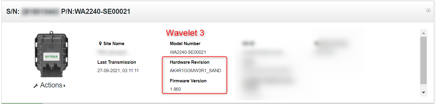
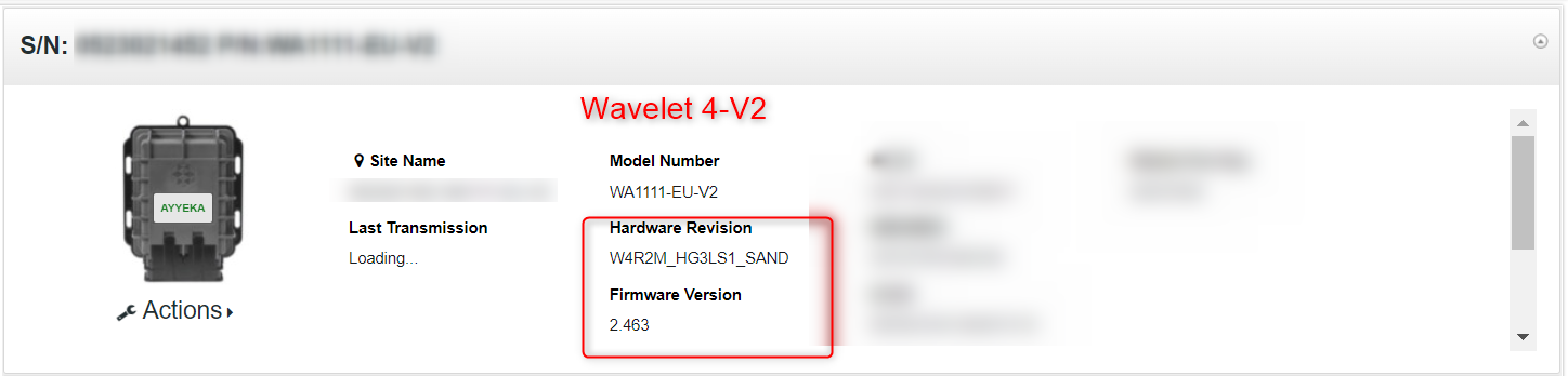
Preliminary Step: Determining your Wavelet type
Some of the connection instructions may differ, depending on the type of the device - Wavelet 3™, Wavelet 4™, Wavelet Ex™, or a Wavelet V2™ . Therefore, the first step is to ascertain the type.
To find your Wavelet version:
- In the left pane, click Devices.
- In the Sites Tree pane, select the relevant site and the relevant device.
- In the right pane, the HW field indicates the Wavelet type. The following screen captures show a Wavelet 3 and a Wavelet 4.
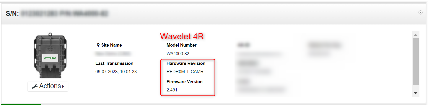
4. Do either of the following actions:
-
- If your device is a version 3, contact support@ayyeka.com for instructions.
- If your device is a version 4, continue following the instructions below.
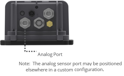
Step 1: Learning the analog port pinout
You can connect the sensor directly to the Wavelet 4 analog port, or connect to it via an Ayyeka analog cable splitter. The analog port is identical in both cases: an 8-pin male connector (the mating field attachable connector is 8-pin female).
To learn about the analog port pinout, refer to one of the following:
Analog Connector Pinouts
The analog port is an 8-pin male connector (the mating field attachable connector is 8-pin female).
See the pinout sheet in the back of the Quick Start Guide.
Analog Cable Splitter Pinouts
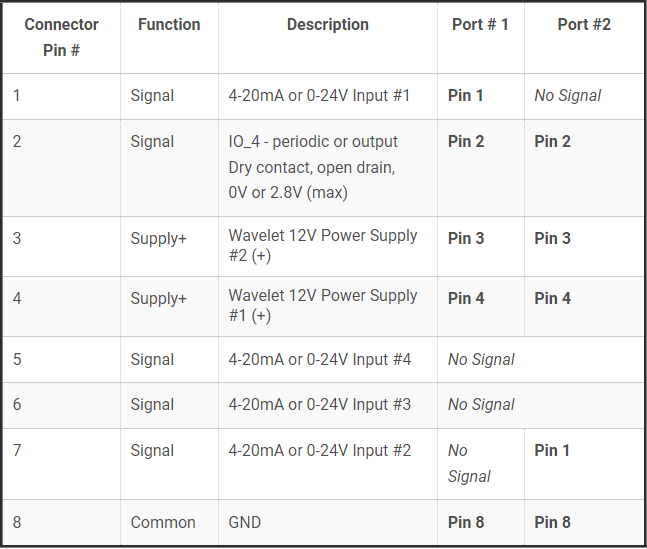
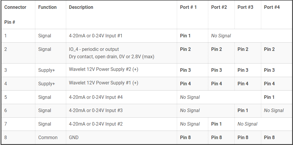
Each analog port on the analog cable splitter is an 8-pin male connector (the mating field attachable connector is 8-pin female). However, the 2-port and 4-port analog cable splitters do not have a pin-to-pin connection to the panel connector on the Wavelet. Please note the pinout below for the cable splitters.
The signal is always wired to connector pin #1, while the signal corresponds to the sensor port number (P1, P2, P3, P4) shown on the cable splitter. For example, when using a 2-port analog cable splitter with two sensors, both sensors are wired for the 4-20mA signal to connector pin #1. Connector pin #1 on sensor port P1 corresponds to 4-20mA Input #1, while connector pin #1 on sensor port P2 corresponds to 4‑20mA Input #2.
 |
 |
| 2-Port Ayyeka Analog Cable Splitter | 4-Port Ayyeka Analog Cable Splitter |
For details, see the 2-Port Analog Cable Splitter pinout sheet and the 4-Port Analog Cable Splitter pinout sheet.
Step 2: Connecting the sensor
A sensor can be connected to the Wavelet in one of two ways, depending on how the sensor receives power:
- The sensor receives power from the Wavelet
- The sensor receives power from an external source
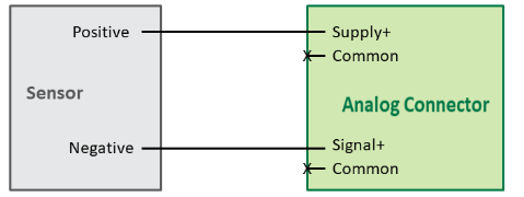
Sensor Receives Power from the Wavelet
In this configuration, you need to:
- Connect the sensor’s Positive pin to the Wavelet analog connector’s Supply+ pin.
- Connect the sensor’s Negative pin to the Wavelet analog connector’s Signal+ pin.
Note that the Wavelet sensor power supply is 250mA, 12VDC.
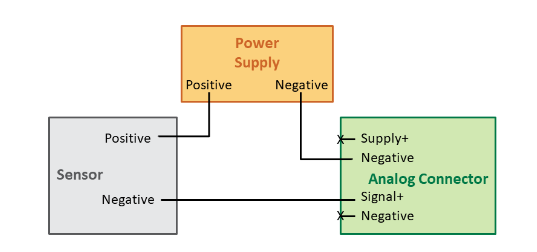
Sensor Receives Power from an External Source
In this configuration, you need to:
- Connect the power supply’s Positive pin to the sensor’s Positive pin.
- Connect the power supply’s Negative pin to the Wavelet analog connector’s Negative (-) pin.
- Connect the sensor’s Negative pin to the Wavelet analog connector’s Signal+ pin
Note that the Wavelet analog connector’s Supply+ pin is not used in this configuration.
Step 3: Configuring sensor settings
After properly wiring the sensor to the Wavelet, configure the sensor’s settings in the management UI. Do the following steps:
- In the left pane, click Devices.
- In the Sites Tree pane, click the relevant device.
- In the right pane, click the Configuration tab.
- In the Configuration tab, scroll down and click Device Advanced Configuration.
- In the configuration tree, click Analog > Channel > 0.
- Click the node called active.
- Right-click the existing value, and then click Set Setting.
- In the New Value field, type in 1, and then click Submit.
- In the configuration tree, click Analog > Channel > 0, and then do the following actions:
- Click the node called channel_type.
- Right-click the existing value, and then click Set Setting.
- In the New Value field, do the following actions, and then click Submit:
- Select CT_CURRENT_1 if you connected the signal to pin 1 of the Wavelet analog port.
- Select CT_CURRENT_2 if you connected the signal to pin 7 of the Wavelet analog port.
- Select CT_CURRENT_3 if you connected the signal to pin 6 of the Wavelet analog port.
- Select CT_CURRENT_4 if you connected the signal to pin 5 of the Wavelet analog port.
For details, see Analog Connector Pinouts.
10. In the configuration tree, click Analog > Channel > 0, and then do the following actions:
-
- Click the node called sample_power_source.
- Right-click the existing value, and then click Set Setting.
- In the New Value field, select the power source, and then click Submit:
- Select PS_INT if the sensor receives power directly from an external source.
- Select PS_EXT1_BOOST if the sensor receives power from the Wavelet, and you connected to the Wavelet power supply through pin 4 of the Wavelet analog port.
- Select PS_EXT2_BOOST if the sensor receives power from the Wavelet, and you connected to the Wavelet power supply through pin 3 of the Wavelet analog port.
For details, see Analog Connector Pinouts.
11. In the configuration tree, click Analog > Channel > 0, and then do the following actions:
-
- Click the node called wakeup_time_ms.
- Right-click the existing value, and click Set Setting.
- In the New Value field, type in the sensor’s wakeup time in milliseconds. For example, if the sensor requires 2 seconds of wakeup time, enter 2000.
- Click Submit.
-
- Click the node called sample interval.
- Right-click the existing value, and then click Set Setting.
- Specify the desired sampling interval in seconds. For more information, see Setting the Stream Sampling Interval.
- Click Submit.
13. In the configuration tree, click Analog > Channel > 0, and then do the following actions:
-
- Click the node called group.
- Right-click the existing value, and then click Set Setting.
- Specify which group to associate the channel with. For more information, see Setting the Stream Sampling Interval.
- Click Submit.
14. Save the configuration changes, and then validate that the device rebooted by doing the following steps:
-
- Click Devices in the left pane, and then select the device in the Sites Tree pane.
- In the right pane, click the Commands tab. You will see a Reboot command after a few seconds.
- If no Reboot command is displayed, click Actions > Reboot in the Device Information pane to manually reboot the device. Both the configuration changes and the reboot will take effect after the device contacts the server.
You can swipe the magnetic Activator key over the embossed logo on the face of the device to force a device reset, which can expedite the time for the Wavelet to connect to the server.
Step 4: Verifying sensor installation
Following the configuration of sensor settings, use the management UI to verify that the sensor is correctly installed and communicating. Do the following steps:
- In the left pane, click Devices.
- In the Sites Tree pane, select the relevant site.
- Select the relevant device.
- Select the stream corresponding to the sensor.
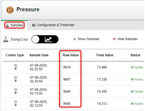
- In the Samples tab, see the Raw Values, which are displayed in units of microamperes (µA).
-
- Raw Values below 3,500 or above 20,500 indicate either improper sensor configuration in the UI (such as a configured sensor wake-up time that is too short) or hardware incompatibility with the Wavelet (such as a sensor that requires a higher voltage than the 12V provided by the Wavelet). See Raw Values of a 4-20 Analog Sensor are Out of Range in the Support section.
-
- Raw Values close to 4,000 indicate the sensor is connected, but has no medium to sample (for example, the sensor is a hydrostatic water level sensor, but it is not submerged in water). Try to provide a medium (such as water).
- Raw Values between 4,000 – 20,000 indicate the sensor is connected correctly and is receiving data.
- Values close to 20,000 indicate the sensor is connected correctly and is receiving data, but has reached its maximum output range.
Step 5: Setting the engineering values
You can define the formula used to convert the raw sampling data into engineering units if the formula being used is linear.
Example 1:
Let's say that you have the analog sensor SE00138 Pressure Sensor, 0-13.8 bar (0-200 psi). You need to convert the raw data (in Raw Value column of the Sample tab) to engineering units that correspond to 0-200 psi range (in Final Value column of the Sample tab).
Example 2:
In this example you have the analog sensor SE00197 Pressure Sensor - Absolute, 0-13.8 bar (0-200 psi). Instead of using the sensor's range of 0-200, you want to set the lower limit to be the ambient pressure in the pipe. The sensor will read the ambient pressure a few minutes after it is connected to the Wavelet. So, for the Final Value, you set the ambient pressure (in psi) to be the lower limit and the upper limit will still be 200psi as defined by the upper range of the sensor.
To change the formula for converting raw data to engineering units:
- In the left pane, click Devices.
- Click the stream name in the Sites Tree pane.
- In the right pane, select the Configuration & Threshold tab.
- In the Configuration & Threshold tab, click the pencil icon
 in the Convert To Engineering Units area.
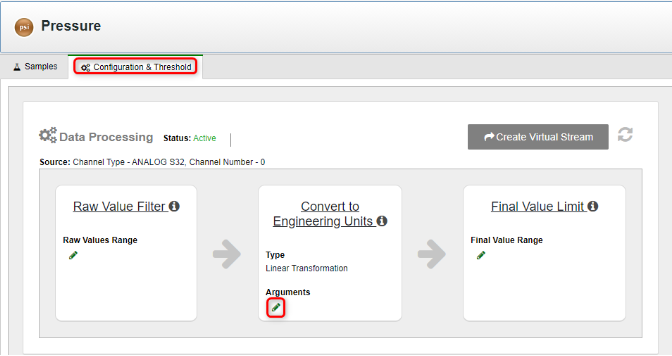
5. In the Update Linear Transformation window that appears, click the Beaker  icon.
icon.
6. Define a formula by entering two pairs of values. The system will compute the actual formula from the values you enter. Do the following actions:
For Example 1:
-
- In the Raw Value column, enter 4000 (4 mA) for Sample 1 and 20000 (20 mA) for Sample 2.
- In the Final Value column, enter appropriate stream minimum and maximum values for the sensor.
In our example, the pressure sensor range is 0-200 psi. You would enter 0 as the Final Value of Sample 1, and enter 200 as the Final Value of Sample 2. The Raw Value and Final values will be: 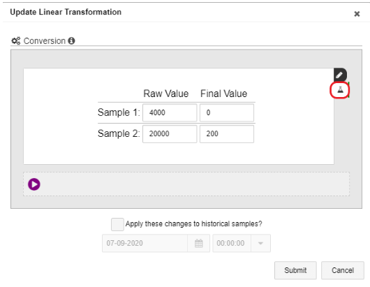
For Example 2:
-
- In the Raw Value column, enter 4000 (4 mA) for Sample 1 and 20000 (20 mA) for Sample 2.
- In the Final Value column, enter the ambient pressure in the pipe for Sample 1 and 20000 (20mA) for Sample 2.
- Optionally, you may Update old samples to retroactively update old samples according to the new conversion formula. You can update samples up to two weeks back.
- Click Submit. The system will compute the conversion formula based on the values you entered.