The sensor is not sampling data
Recommended actions
Get the following information:
- Is the sensor supported? See the list of supported sensors.
- If the sensor is not listed, then it is not supported. Ask Support for information about unsupported sensors.
- If the sensor is supported, check its data sheet.
- If the sensor is in a serial channel and uses Modbus communication, check the sensor's User Manual for Modbus configuration. Note especially what the offset and the endian type (big endian or little endian) are.
- Check the sensor's channel configuration (see Advanced Configuration for Analog, Digital, and Serial channels):
- In the STREAM MANAGEMENT table for the device, note which sample group the channel belongs to, and then go to SampleGroup > GROUP > sample_group_# .
- The parameter group_active must be set to AS_ON or AS_ON_HOLD.
- If the value of group_active is AS_ON_HOLD, check that an actual Event triggered the group sample.
- The parameter group_sample_interval_sec must be greater than 0.
- From FW 2.32.x and newer, every channel must be in a group. Any channel that is not in a group will not sample at all (with the exception of a digital sensor).
- wake_time (or wakeup_time)
- sensor_power_source (serial channel) or sample_power_source (analog channel)
- sample_handler
- read_addr
- slave_addr
- Was the sensor giving good values, and then suddenly stopped? If so, check the following items:
- Commands that were sent just prior to the loss of data
- Boot count (was there a reset?)
- Battery and external power (if used), did all streams stop or just one particular one? (check in the Visualization window).
- Check all channels connected to that sensor (in STREAM MANAGEMENT table). Is one channel of the sensor not showing values or are all channels not showing values?
- Was there any physical maintenance on site such as site maintenance, swap sensors, disconnect the sensor, replace desiccants in the device, replace the battery
- Restore configuration (click Actions > Restore Configuration) to send all settings in UI to the device.
- If the sensor never worked, request pictures of wiring and installation (if relevant).
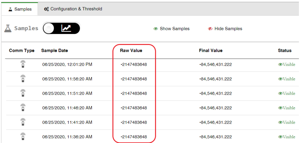
Data samples from the serial sensor show Modbus errors
The serial channel is working because the sensor is attempting to sample data. There are values, but the values are all modbus errors (-2147483648).
Recommended action:
- Check the configuration of the sensor. Check the power source of the sensor:
-
- If the sensor has its own power source, check the state of (sensor_power_source).
- If the sensor is getting power from the device and the battery is low, sampling might stop.
-
- Commands that were sent just prior to the loss of data
- Boot count (was there a reset?)
- Battery and external power (if used), did all streams stop or just one particular one? (check in the Visualization window).
- Check the Internal Humidity technical stream for moisture in the housing.
- Check all channels connected to that sensor (in STREAM MANAGEMENT table). Is one channel of the sensor not showing values or are all channels not showing values?
- Was there any physical maintenance on site, such as site maintenance, swapping sensors, disconnecting the sensor, replacing desiccants in the device, replacing the battery?
Ultrasonic sensor displays outlying values from normal measurement
Every ultrasonic sensor is sensitive to interference from mist, foam, turbulence, and so forth. Consequently, outlying values should be expected from time to time.
To hide these outlying values from your graph reports and APIs, see Viewing and Editing the Treatment of Raw Data. The data will still be displayed in the Samples tab as a Hidden value.
Alternatively, if you're seeing outlying values often, re-evaluate the type of ultrasonic sensor that you're using. Check that it is suitable for your specific environment. If needed, contact Support.
Raw Values of a 4-20 Analog Sensor are Out of Range
Perform the following checks if the raw values received from the sensor are below 3,500 µA or above 20,500 µA.
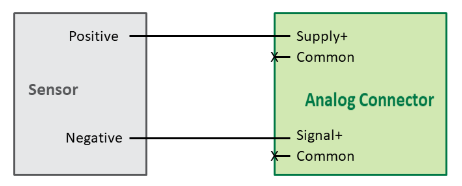
Measuring voltage at the analog port
- When the device is on, connect a voltmeter to the analog port pins, as follows:
-
- If this is an installation where the sensor receives power from the device, connect the voltmeter to the Supply+ and Negative (-)
- If this is an installation where the sensor receives power directly from an external source, connect the voltmeter to the Signal+ and Negative (-)
Note that power is not supplied continuously, but only for short bursts of time, depending on the configured sampling interval and duration. Typically, the sampling interval is between 1‑5 minutes, and the sampling duration is between 100 ms – 2 sec.
2. Note the voltage:-
- If the voltage is 12V, then proceed to measuring voltage on the analog cable.
- If the voltage is not 12V, the device may be damaged, off, or configured incorrectly. Contact Ayyeka for technical support.
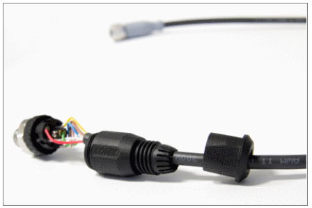
Measuring voltage on the analog cable
- Carefully open the housing of the field attachable connector on the cable of the sensor connecting to the device, to expose the wires (conductors). Be sure not to forcefully twist the wires while opening the connector housing.
- Connect a voltmeter to the exposed Signal+ and Negative (-).
- Note the voltage:
-
- If the voltage is between 0.4 – 2.1V (which corresponds to 4,000 – 20,000 µA), then proceed to Measuring current between the sensor and the device.
- If the voltage is not between 0.4 – 2.1V, then the sensor connections to the Wavelet are incorrect, loose, or damaged. If you need assistance, contact Ayyeka for technical support at support@ayyeka.com.
Measuring current between the sensor and the device
- Use an Ampere meter to measure the current between the Wavelet and the sensor cable, by connecting the Signal+ pin on the Wavelet analog connector with the Negative (-) pin on the sensor cable connector.
- Note the current:
-
- If the value is not between 4 – 20mA, then either the sensor is damaged, or the sensor connections to the device are incorrect, loose, or damaged.
- If the value is between 4 – 20mA, then either the device is damaged, or it is configured incorrectly. Contact Support for additional support.