Contents
Data Handling by the Serial Sensor
Communication Packet Structure
Putting it all Together - Modbus Messages
Accessing a channel’s advanced settings
Description of parameters that are common to all serial protocols
graph_normalizer_a, graph_normalizer_b, graph_normalizer_c
graph_level_index, graph_level_count
Parameter that defines which serial communication protocol to use
Parameters for all serial protocols except Column Parser
Parameters only for Modbus serial protocol
read_flag
Overview of the Serial Sensor
A serial sensor is a device that measures some physical entity and provides measured information by using a computational component through a serial communication channel.
Serial communication sends data one bit at a time, sequentially, by using a pre-defined protocol.
A Wavelet serial channel can support different communication protocols: Modbus (RTU and ASCII), SDI12, Column Parser (column-based, ASCII stream), and proprietary protocols (Ponsel, Flow-Tronic, and SEBA Hydrometrie).
The physical protocols RS-232, RS-485, and SDI12 are supported.
Note: If you use a serial cable splitter, only one of the ports can be RS-232. The remaining ports can be any combination of one or more RS-485 and SDI-12 sensors.
Serial Topology
RS-232 and RS-485 are standard protocols for serial data transmission. A benefit of the RS-485 protocol is the ability for several devices to share the same bus. As a result, you do not need multiple RS-485 interfaces to query multiple devices.
Data Handling by the Serial Sensor
The serial sensor obtains raw data by sampling it every configurable number of minutes. You can smooth out short-term fluctuations in the data and highlight longer-term trends by using data smoothing and moving average techniques.
Data Smoothing
Data smoothing is done in two stages to smooth the raw data points:
- Stage 1: Apply a graph-normalizer to the data points that are the output of stage 1. The resulting values are now considered the raw data points.
- Stage 2: Apply a moving average to the data points that are the output of stage 1. In Serial, the moving average is always the mean The resulting values are now considered the raw data points.
Both stages are optional. You can elect to skip either or both stages.
Moving Average
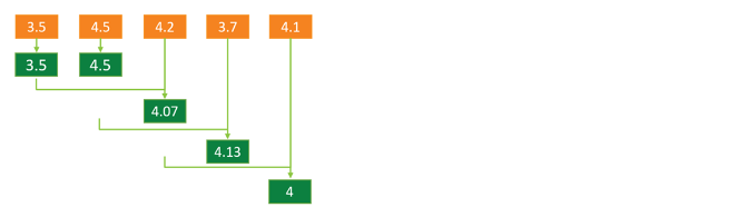
Moving average is a calculation that creates a series of averages of different subsets of the full data set. Specifically, the moving-average of a given data point, is the mean of the Z most recent data points, where Z is the graph_mean_count number.
For example, if the graph_mean_count=3, then the moving-average of a given data point is the mean of the following 3 data points: the given data point and the two preceding data points.
Important: If you elect to apply a moving average to raw data, then the output of the process is henceforth considered the raw data – both as regards the display of the raw data in the UI, and as regards further manipulation of raw data.
Example:
If the given raw data points are 3.5 4.5 4.2 3.7 4.1, and you applied a moving average of 3, then the resulting moving average values are now considered the raw data points: 3.5 4.5 4.07 4.13 4.
Overview of Modbus
Modbus is a serial communication protocol that transmits data and commands between devices over serial lines.
In Modbus architecture, there are two roles: master and slave. The device that sends a request for information is called the master. The device that responds and supplies that information is called the slave.
The master will write data to and read data from a slave device’s registers. A reference to a register or to a register address is always in the context of the slave’s registers. When several slave devices are connected to the same RS-485 bus, each slave device must have a unique slave address.
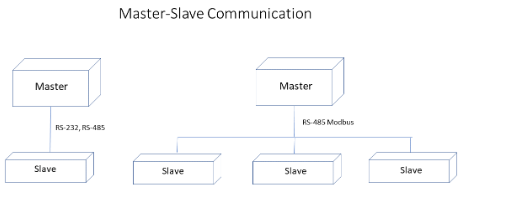
When Modbus protocol is used, a Wavelet takes the role of Modbus master, and the sensors are the slaves.
The Wavelet and sensors communicate by using the Modbus RTU (Remote Terminal Unit) or Modbus ASCII versions over RS-232 and RS-485 serial ports. The Wavelet requests a data sample from the sensor, and the sensor responds by sending data to the Wavelet.
The master can also write information to the slaves. The Wavelet can update or configure some sensors.
For Modbus communication to work correctly, the master and all slaves must meet the following requirements:
- Each slave is properly configured with a unique address.
- All devices have the same baud rate and parity.
- All devices use the same Modbus protocol – either RTU or ASCII.
For more information about Modbus, see Modbus 101 – Introduction to Modbus.
Modbus RTU versus ASCII
Modbus RTU employs binary coding and cyclic redundancy checking (CRC) for errors when sending messages. As a result, this method of communication is the protocol that is typically used. Messages are sent in binary format.
In contrast, Modbus ASCII uses ASCII characters and longitudinal redundancy checking (LRC) for errors. This method of communication is less efficient and has a lower degree of error checking.
Modbus RTU and Modbus ASCII both work with serial devices, but they are incompatible with each other.
Communication Packet Structure
Coils and Registers
Modbus messages relay read and write operations on four different types of memory.
- Two types of memory store discrete values in Coils and Discrete Input.
A discrete value is in a 1-bit address. Single bit addresses are used to represent TRUE/FALSE or ON/OFF states.
An example of Coils is a relay output.
An example of Discrete Input is sensor input such as switches.
- Two other types of memory store continuous values in a Holding register or in an Input register.
A continuous value is in a 16-bit (=2 bytes =1 word) register. The register is either signed or unsigned 16-bit integer. If a 32-bit integer or a floating point is needed, the value is in a pair of registers.
The most commonly used register is the Holding register. The following table describes a Holding register:
|
Coil or Register Numbers |
Data Addresses |
Offset |
Type |
Goes to This Modbus Table in Memory |
|
1-9999 |
0000 to 270E |
1 |
Read-Write |
Modbus Coils |
|
10001-19999 |
10001 |
Read only |
Modbus Discrete Inputs |
|
|
30001-39999 |
30001 |
Read only |
Modbus Input Registers |
|
|
40001-49999 |
40001 |
Read-Write |
Modbus Holding Registers |
Function Codes
Function codes define the type of register being addressed by a Modbus request. The following table lists the function code and the type of registers that it addresses.
|
Function code |
Register type |
|
1 |
Read Coil |
|
2 |
Read Discrete Input |
|
3 |
Read Holding |
|
4 |
Read Input |
|
5 |
Write Single Coil |
|
6 |
Write Single Coil Holding |
|
15 |
Write Multiple Coils |
|
16 |
Write Multiple Holding |
A complete definition of where to find a piece of data requires both the address and the function code.
Putting it all Together - Modbus Messages
Each data packet of the message, whether request or response, has the following components:
- Slave address that identifies the specific slave device
- Function code that tells the slave which Modbus register type to access and whether to read from or write to
- Parameters that define what is being asked for or provided
Byte and Word Ordering
The Modbus specification does not define exactly how the data is stored in the registers. Therefore, some manufacturers implemented Modbus in their equipment to store and transmit the higher byte first followed by the lower byte. Alternatively, others store and transmit the lower byte first.
Similarly, when registers are combined to represent 32-bit data types, some devices store the higher 16 bits (high word) in the first register and the remaining low word in the second, while other devices do the opposite. The receiving device must know the order in which the bytes or words are sent.
You configure this order in the UI’s Advanced Device Configuration window for the Serial channel. See the section Parameters only for Modbus serial protocol below.
Example
Suppose that the number 2,923,517,522 (hexadecimal form is AE41 5652) will be sent as a 32-bit unsigned integer. The following figure shows the high byte, low byte, high word, and low word of the integer.
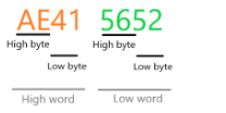
The manufacturer can implement Modbus storage of this data in any of the following four ways:
|
Word-Byte Arrangement |
High Word first (outer) |
Low Word first |
||
|
High Byte first (inner) |
Low Byte first |
High Byte first |
Low Byte first |
|
|
AE41 5652 |
X Outer big, inner big |
|
|
|
|
41AE 5256 |
|
X Outer big, inner little |
|
|
|
5652 AE41 |
|
|
X Outer little, inner big |
|
|
5256 41AE |
|
|
X Outer little, inner little |
|
For further details about Modbus, see Simply Modbus, Frequently Asked Questions.
Glossary of Modbus terms
- Master – The devices that sends a request for information (the Wavelet).
- Slave – The device that supplies the information that the master requested. Every slave has a unique 8-bit device address.
- Slave Address – The address of the slave device (the sensor).
- Register –16 bits of unsigned data. If a 32-bit integer or floating point is required, these values are read as a pair of registers. There are two types of registers: input (a place for data coming in) and holding (holds data to be processed).
- Register Address – The address of the slave device’s (sensor) register that the master (Wavelet) writes data to and reads data from.
 Accessing a channel’s advanced settings
Most device configuration actions are performed in Transmission Interval and the Stream Management sections of the ![]() graphic user interface (GUI). However, certain advanced configuration tasks can only be done using the Device Advanced Configuration hierarchical tree, available also through the GUI.
graphic user interface (GUI). However, certain advanced configuration tasks can only be done using the Device Advanced Configuration hierarchical tree, available also through the GUI.
See Overview, Account Hierarchy, and Data Model Hierarchy for an overview of the device.
Prerequisite:
If you are setting up a Modbus channel, you must have the sensor's Modbus documentation. You will need to define the parameters in Description of parameters that are common to all serial protocols.
To access a channel’s advanced settings:
- Click Devices in the left pane.
- In the Sites Tree pane, select the device.
- In the right pane, click the Configuration.
- In the Stream Management table, locate the desired stream’s channel number in the # column. For example, the channel number might be 0.
- Scroll down past the Stream Management table, and then click Advanced Device Configuration.
- Check the parameter values for all sample groups. For details of the parameters and their values, see Configuring SampleGroup (Group of Sensors in a Channel).
- In the Advanced Device Configuration tree, click Serial to expand it.
- Click Channel to expand it.
- In our example, select 0 under the Channel node because in Step (4) we decided to configure that channel.
- Configure the parameters that are nested under the channel number node, as described in the following sections:
a. Parameters common to all serial protocols
b. Parameters that define which serial protocol to use
c. Parameters only for Modbus serial protocol
Note: Channel configuration parameters are applied to the channel in addition to the other channel parameters, such as Thresholds.
TIP: If the sensor uses Modbus communication, check the sensor's User Manual for Modbus configuration. Note especially what the offset and the endian type (big endian or little endian) settings are. You might need to do some trial-and-error testing with these parameters to get sampling.
To see a sample Modbus serial sensor configuration, see Configuring a Modbus Serial Sensor.
11. Save the configuration changes, and then validate that the device rebooted by doing the following steps:
a. Click Devices in the left pane, and then select the device in the Sites Tree pane.
b. In the right pane, click the Commands tab. You will see a Reboot command after a few seconds.
c. If no Reboot command is displayed, click Actions > Reboot in the Device Information pane to manually reboot the device.
Both the configuration changes and the reboot will take effect after the device contacts the server.
Description of parameters that are common to all serial protocols
bus_baud
|
Description: |
Defines the baud rate of the serial bus. The baud rate of the master and the slaves must be the same. Select the baud rate that is given in the hardware specifications of the sensor. |
|
Note: |
All channels in the same group must have the same baud rate. |
|
Options: |
Typically, baud rates are 9600, 19200, and 115200. |
bus_parity
| Description: |
Bit parity is used to indicate if all data was transmitted successfully. The bit parity of the master and the slaves must be the same. Select the bus parity that is given in the hardware specifications of the sensor. |
| Options: |
BUS_PARITY_NONE BUS_PARITY_ODD BUS_PARITY_EVEN |
interface_type
|
Description: |
Defines the type of serial port. Select the type of serial port that is given in the hardware specifications of the sensor. |
|
Options: |
IT_RS232 – Pins 1 and 7 IT_RS485 – Pins 5 and 6 IT_SDI12 – Pin 4 |
active
|
Description: |
Defines the channel’s state as enabled or disabled. |
|
Options: |
AS_OFF – Default. Channel is inactive/disabled. No samples will be recorded. AS_ON – Channel is active/enabled. Samples will be recorded. AS_ON_HOLD – Channel is active and waiting for a trigger to instantiate. In FW version 2.320 and newer, this value cannot be used. If a channel needs to be on hold, do the following steps:
|
wake_time_ms
|
Description: |
Specify the length of time, in milliseconds, that the sensor needs to completely power up and calibrate before the device requests a sample from the sensor. This parameter defines the sensor boot time and stabilization time. If data sampling is done before the sensor has completely booted up and stabilized, the data sampling might be incomplete or its values might be erratic. Note that the frequency at which the sensor is powered on is determined by the sample_interval. |
| Example: |
Suppose the wakeup time interval of the sensor is 500ms. The device takes a sample 500ms after the sensor is powered on. Note: If the channel is in a group, then the wakeup time interval will be the maximum time of all channels in the group.
|
sample_interval
The sample_interval value is relevant only when the Firmware is older than version 2.301 and when Group is set to 0. Otherwise, this parameter is ignored because sampling is done only for a group of channels (use group_sample_interval_sec).
sample_interval_type
The sample_interval_type value is relevant only when the Firmware is older than version 2.301 and when Group is set to 0. Otherwise, this parameter is ignored because sampling is done only for a group of channels (use group_sample_interval_type).
graph_normalizer_a, graph_normalizer_b, graph_normalizer_c
|
Description: |
The graph is normalized by setting three parameters a, b, and c in graph_normalizer_a, graph_normalizer_b, and graph_normalizer_c respectively. To every data point value x, we apply the following normalizer function: y=(a/b)*x + c The preferred method to set the values for a, b, and c is in the Configuration tab of the stream (Devices > Specific stream > Configuration tab). |
|
Important: |
If you elect to apply a graph normalizer, then the normalized output is henceforth considered the raw data, which will be displayed in the UI and will be used in any further manipulation of raw data. |
|
Examples: |
If the given raw data points are: 6.5 4.5 6.07 6.13 6 And you applied a normalizer with a = 10, b = 1, c = 0 Then, the resulting normalized values are now considered the raw data points: 65 45 60.7 61.3 60 If you do not wish to apply a graph normalizer, set the following values: a = 1 In effect, the data point values remain unchanged. |
graph_mean_count
|
Description: |
Specify whether to apply the last of the two optional data smoothing measures to the raw data points. This last stage again employs the Moving average mechanism, but its degree of smoothing is determined by the value you specify in graph_mean_count. The values obtained after applying this final smoothing measure, appear as the raw sample values in the Samples table. |
|
Options: |
Specify 0 or 1 if you do not wish to apply this second stage data smoothing measure to data points. The data point values remain unchanged. Specify a whole number greater than 1 if you wish to apply this stage of data smoothing measure to the data point values. See Moving average for a full description. The maximum allowed value is 10. |
graph_level_index, graph_level_count
|
Description: |
These settings are populated by the Thresholds definitions set in the GUI. |
group_priority
|
Description: |
If several channels are assigned to the same group, this parameter determines in which order the sensors will be sampled. The channel with the highest group_priority number is sampled first, then the channel with the second highest group_priority number, and so forth. |
sensor_power_source
|
Description: |
Defines the sensor’s expected power supply. |
Device Pin Assignment Front |
|||
|
Options: |
PS_INT – Power is supplied by an external power source (not the Wavelet). |
|
|||
|
PS_EXT3 – Power is received from the serial connector’s Pin 3, at an operating voltage of 3.6V PS_EXT4 – Power is received from the serial connector’s Pin 2, at an operating voltage of 3.6V |
 |
||||
|
PS_EXT3_BOOST – Power is received from the serial connector’s Pin 3, at an operating voltage of 12V PS_EXT4_BOOST – Power is received from the serial connector’s Pin 2, at an operating voltage of 12V |
 |
||||
|
Notes: |
To select other power sources, contact support@ayyeka.com. Most sensors require at least 6V, so you will typically need either PS_EXT3_BOOST or PS_EXT4_BOOST. In Wavelet 4R™, the single panel connector port has connector pins for analog, serial, and digital. In this device, use PS_EXT1_BOOST. In general, when there are two or more serial sensors, they can each share the same Wavelet output power source (such as Pin 3). However, when the serial sensors have different wake-up times, or they are in different sample groups that have different sample intervals, it is recommended to connect the sensors to different power source pins. For detailed serial connector pinout information, see the back pages of the Quick Start Guide for your device. |
||||
modbus_reset_on_startup
|
Description: |
Write a value to a register before the register is read. You might need to do this when you configure a sensor. The value is defined in extra_params. |
|
Options: |
TRUE (1) or FALSE (0) |
Reset delay
|
Description: |
The amount of time in milliseconds to wait between powerup and resetting the register. If modbus_reset_on_startup is disabled, then this parameter is also disabled. |
Data bits
|
Description: |
Data is transmitted as a series of seven, eight, or nine bits with the least significant bit sent first. Select the number of data bits that is given in your hardware specification. |
|
Options: |
DB_7 – 7 data bits DB_8 – 8 data bits DB_9 – 9 data bits |
Stop bits
|
Description: |
The stop bit signals the end of a data packet transmission. Select the number of stop bits that is given in your hardware specification. |
|
Options: |
SB_1 – 1 stop bit SB_1_5 – 1.5 stop bits SB_2 – 2 stop bits |
Parameter that defines which serial communication protocol to use
Sample_handler
|
Description: |
The communication protocol that is used by the application. Select the protocol based on the type of sensor. |
|
Options: |
SH_MODBUS_RTU – Uses Remote Terminal Unit (RTU) mode that sends each 8-bits in a message as two hexadecimal characters. You can define extra parameters. SH_MODBUS_ASCII – Uses American Standard Code for Information Interchange (ASCII) mode that sends each 8-bits in a message as two ASCII characters. You can define extra parameters. SH_SDI12 - An asynchronous serial communications protocol for intelligent sensors that monitor environmental data, and usually communicate with a data logger or other data acquisition device. SH_KEPMETER – Uses the KEP serial communication protocol. SH_COLUMN_PARSER – Parses each ASCII message by column. Proprietary protocols:
|
Parameters for all serial protocols except Column Parser
slave_addr
|
Description: |
The address of the sensor that is given in your hardware specification. For example, 1. Note: The slave address must be entered in decimal (not hexadecimal).
|
read_addr
|
Description: |
The address of the register to read. The address is given in your hardware specification. For example, 303 or 40303. Sensors can be zero-based or one-based. Consequently, the read_addr might need to be offset by +1 or -1. The device is zero-based. Note: The read address must be entered in decimal (not hexadecimal).
|
|
Examples: |
|
Parameters only for Modbus serial protocol
TIP: If the sensor uses Modbus communication, check the sensor's User Manual for Modbus configuration. Note especially what the offset and the endian type (big endian or little endian) settings are. You might need to do some trial-and-error testing with these parameters to get sampling.
read_type
|
Description: |
In Modbus RTU, data is most often read and written as registers, which are 16-bit pieces of data. Most often, the register is either a signed or unsigned 16-bit integer. If a 32-bit integer or floating point is required, these values are read as a pair of registers. The most commonly used register is called a Holding Register, and these can be read or written. Holding Registers can be signed, unsigned, float, and double 8-16-32 bits. The other possible type is Input Register, which is read-only. Input Registers can be signed or unsigned 8-16-32 bits. The read type is given in your hardware specification. |
|
Notes: |
This parameter is relevant only if the parameter sample_handler is SH_MODBUS_RTU. |
|
Options: |
MODBUS_READ_HOLDING_U8 MODBUS_READ_HOLDING_U16 MODBUS_READ_HOLDING_U32 MODBUS_READ_HOLDING_S8 MODBUS_READ_HOLDING_S16 MODBUS_READ_HOLDING_S32 MODBUS_READ_HOLDING_FLOAT MODBUS_READ_HOLDING_DOUBLE MODBUS_READ_INPUT_U8 MODBUS_READ_INPUT_U16 MODBUS_READ_INPUT_U32 MODBUS_READ_INPUT_S8 MODBUS_READ_INPUT_S16 MODBUS_READ_INPUT_S32 MODBUS_READ_INPUT_FLOAT MODBUS_READ_INPUT_DOUBLE MODBUS_READ_DISCRETE_INPUT MODBUS_READ_ DISCRETE_OUTPUT |
read_flags
|
Description: |
Choose whether the high order or the low order register is read first, according to the sensor specifications. “Inner” refers to the byte order, and “outer” refers to the word order. “Little” refers to the least significant byte or word first. “Big” refers to the most significant byte or word first. For details and an example, see Byte and Word Ordering. |
|
Options: |
MODBUS_FLAGS_OUTER_BIG_INNER_BIG MODBUS_FLAGS_ OUTER _BIG_INNER_LITTLE MODBUS_FLAGS_ OUTER _LITTLE_INNER_BIG MODBUS_FLAGS_ OUTER _ LITTLE _INNER_ LITTLE |
extra_params
|
Description: |
When sample_handler is set to SH_MODBUS_RTU or to SH_MODBUS_ASCII, three additional parameters can be defined:
This parameter is enabled when modbus_reset_on_startup reset flag is set to TRUE (1). 3. Float or double multiplication factor that converts a float or a double to a 32-bit signed integer. For example, the multiplication factor of 1000 converts 1.23456 to 1234. The decimal part of the value is truncated off. This parameter is used if the read_type is defined as any of the following types:
|
||||||||||||
|
Options: |
Use the format: attempts,reset_value,multi_factor. Important: Use a comma (,) as a separator between values. Do not add any spaces. You can set any of the three parameters. The default values are: 8,0,1000. For the default value, use an asterisk (*). The following table lists the valid values for each parameter and describes how values that are not valid are handled.
|
||||||||||||
|
Examples: |
Example 1:
The device will try to read the register up to three times. Before that, it will write 50 to the same register. After the device reads a value, it will multiply it by 100000. Example 2:
The device will try to read the register up to two times. Before that, it will write 1 to the same register. After the device reads a value, it will multiply it by 1000. Example 3:
The device will try to read the register up to eight times. Before that, it will write 34 to the same register. After the device reads a value, it will multiply it by 1000. Example 4:
The device will try to read the register up to three times. Before that, it will write 0 to the same register. After the device reads a value, it will multiply it by 1000. Example 5:
The device will try to read the register up to 8 times. Before that, it will write 0 to the same register. After the device reads a value, it will multiply it by 1000. Example 6:
The device will try to read the register up to three times. The second parameter, 50, is ignored because Startup reset flag is not TRUE. After the device reads a value, it will multiply it by 100000. In all examples, the third parameter is used only if the read_type is defined as any of the four types that are listed above. |