Contents
Introduction to Digital Channel Advanced Configuration
First Things First: Is This an Input or an Output Channel?
Accessing a Channel’s Advanced Settings
Configuring an Input Channel’s Advanced Settings
Step 1: Determine the Input Channel Type
Step 2: Set an Input Channel’s Advanced Settings
Description of an Input Channel’s Advanced Settings
pcnt_sample_interval_sec
graph_normalizer_a, graph_normalizer_b, graph_normalizer_c
Configuring an Output Channel’s Advanced Settings
Appendix A: Correlation between Event and Polarity
Appendix B: Description of an Output Channel’s Advanced Settings
Appendix C: Digital Connector PinoutsIntroduction to Digital Channel Advanced Configuration
Most device configuration actions are performed in the Transmission Interval and the Stream Management sections of the Ayyeka graphic user interface (GUI). However, certain advanced configuration tasks can only be done using the Device Advanced Configuration hierarchical tree, available also through the GUI. One of those tasks is the advanced configuration of a device’s digital channel (which accepts only a logical 0 or 1). This article describes that task.
Note that the digital channel configuration you set through the Advanced Configuration tree is applied to the channel in addition to the other channel settings you set graphically through the GUI (such as Threshold definitions, described in Configure Data Stream Thresholds and Alerts).
Terminology
A digital signal has two possible states. In professional literature, these two states are referred to in various terms, among them:
- A pulse / No pulse
- Closed circuit / Open circuit
- High state / Low state
- Digital signal / No digital signal
- '1' / '0'
- Logic one / Logic zero
- True / False
- 2.8V / 0V
First Things First: Is This an Input or an Output Channel?
Advanced channel configuration is useful both in scenarios where the device receives incoming (Input) signals from equipment connected to the device connector, and in scenarios where the device sends (Output) signals from the device to equipment connected to the device connector.
The device is mostly used in Input scenarios (such as those described in Examples of digital sensors), where you connect a sensor to the device's digital connector and receive incoming signals from the sensor.
An example of an Output scenario is one where you connect to the device’s digital connector a pump, which starts operating when it receives a pulse from the device. You could then configure a Threshold Action for some water level channel, which instructs the device to send an output signal to the pump – thus effectively activating the pump – when water level exceeds the defined threshold.
Depending on whether the channel is an input or output channel, refer to either:
Accessing a Channel’s Advanced Settings
To access a channel’s advanced settings:
- Click Devices in the left pane.
- In the Sites Tree pane, select the device.
- In the right pane, click the Configuration tab.
- In the Stream Management table, locate the desired stream’s channel number in the # column. For example, suppose that the channel number of the Float Switch stream is 0.
- Scroll down past the Stream Management table, and then click Advanced Device Configuration.
- Check the parameter values for all sample groups. For details of the parameters and their values, see Configuring SampleGroup (Group of Sensors in a Channel).
- In the configuration tree, click Digital to expand it.
- Click Channel to expand it.
- In our example, select 0 under the Channel node because in Step (4) we wanted to configure channel 0.
- Define the channel settings in the parameter nodes nested under the channel number node. Depending on whether the channel is an Input or an Output channel, you can configure an Input channel or configure an Output channel.
Configuring an Input channel’s advanced settings
Examples of digital sensors
In digital Input channel scenarios, you typically connect a digital sensor to the device’s digital connector and receive incoming signals from the sensor. Typical digital sensors include, for example:
- A digital float switch that sends a pulse when the level of liquid is above a certain point, and does not send a pulse when the level of liquid is below a certain point. Thus it can be used to detect whether water level is above a certain level (such as 5 meters) or below.
- A digital flow meter that sends a pulse whenever a certain volume of liquid (such as 5 cubic meters) flows through. By summing the number of pulses sent in a time interval (such as an hour), we can deduce the flow rate during that hour (such as 2 cubic meters/sec).
Step 1: Determine the Input channel type
Before you start configuring Advanced Settings for an Input channel, first determine the desired channel type, that is, how you want data from the sensor to be analyzed and displayed in the UI. Ayyeka offers three digital input channel types:
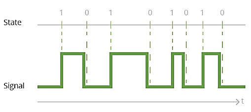
Edge
An Edge scenario is one in which you want an indication every time an "edge" event occurs – such as a switch state changing from closed to open or from open to closed.
A common Edge use-case is a float switch. This means you can, for example, get an indication every time the level of liquid goes above or below a certain level.
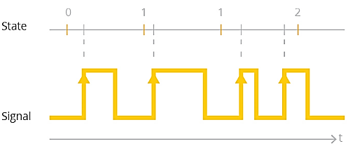
PCNT – Pulse Counter
A PCNT scenario is one in which you want to know how many events occurred in a defined time interval, such as an hour.
PCNT use-cases typically utilize a flow meter sensor. This means you can, for example, learn how many times an hour, a liter of water flowed through a pipe, and thus deduce the pipe flow rate.
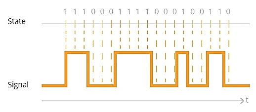
Periodic
A Periodic scenario is one in which you want to know the sensor state at the end of a configurable time interval. For example, you want to know, every five minutes, whether a pump is working or not.
Step 2: Set an Input channel’s advanced settings
To set an input channel’s advanced settings:
- Follow the instructions for Accessing a Channel’s Advanced Settings.
- Configure the parameters nested under the channel number node, as described in Description of an Input Channel’s Advanced Settings below.
Description of an Input channel’s advanced settings
To set the advanced settings of an Input channel, configure the parameters described in this section.
active
|
Description: |
Defines the channel’s state as enabled, disabled, or waiting for an event trigger. |
|
Options: |
Steps to Put a Channel On Hold: In FW version 2.320 and newer, this value cannot be used. If a channel needs to be on hold, do the following steps:
|
location
|
Description |
Defines which pin number on the device’s digital connector port 3 is receiving signals from the sensor. On the Wavelet V2™ device, an additional pin for digital input is on connector port 1 (analog) of the device. |
|
|
Notes |
Important: Locations that are appropriate for your device might vary, depending on the device type. Use the detailed pinout information for your device to select the appropriate value for Location. |
|

|
Value for Location |
Function |
Connector Port on Device |
Pin # on Connector Port |
Found in Which Device |
|
PL_DIGITAL_IO_PCNT_0, PL_MCU_PCNT_0 (old name) |
PCNT, Edge, Periodic, output |
Digital |
1 |
Wavelet 4™, Wavelet V2™, Wavelet Ex™, Wavelet 4R™ |
|
PL_DIGITAL_IO_PCNT_1, PL_MCU_PCNT_1 (old name) |
PCNT, Edge, Periodic, output |
Digital
|
3 |
Wavelet 4™, Wavelet V2™, Wavelet Ex™, Wavelet 4R™ |
|
PL_DIGITAL_IO_2, PL_ACMP_0 (old name) |
Edge, Periodic, output |
Digital
|
5 |
Wavelet 4™, Wavelet V2™, Wavelet Ex™ |
|
PL_DIGITAL_IO_3, VLSense1 (old name) |
Periodic, output |
Digital
|
2 |
Wavelet V2™ |
|
PL_DIGITAL_IO_4, VLSense2 (old name) |
Periodic, output |
Analog |
2 |
Wavelet V2™ |
|
PL_IOEXT_GPIO_1 |
DO NOT USE – Unsupported by hardware and/or firmware |
|||
|
PL_IOEXT_GPIO_2 |
||||
|
PL_IOEXT_GPIO_3 |
||||
|
PL_IOEXT_GPIO_4 |
||||
|
PL_ADS_GPIO_1 |
||||
|
PL_ADS_GPIO_2 |
||||
|
PL_ADS_GPIO_3 |
||||
|
PL_ISO_INPUT_A |
||||
|
PL_ISO_INPUT_B |
||||
|
PL_ISO_OUTPUT_A |
||||
|
PL_ISO_OUTPUT_B |
||||
type
|
Description: |
Defines the Input channel’s Input channel type, which determines how sensor data will be analyzed and displayed. |
|
Options: |
|
polarity
|
Description: |
Specify how to indicate an incoming signal from the sensor. |
|
|
Options: |
|
 |
|
 |
|
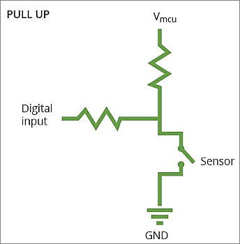
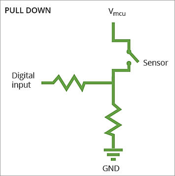
pull
|
Description: |
Specify the function of the pull-up resistor used in the device to ensure a known state for a signal. The resistor is used to raise or lower voltage between pins. |
|
Options: |
|
|
Schematic diagrams: |
|
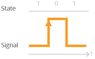
edge_event
|
Description: |
Specify which occurrences are considered events.
Note: This parameter is not relevant for a Periodic channel type. |
|
Options: |
|
|
Note: |
Note that polarity and edge_event are correlated. For more information, refer to Appendix A: Correlation between Event and Polarity. |
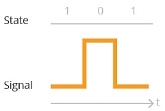
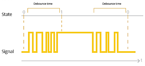
debounce_time_ms
|
Description: |
The time, in milliseconds, that the sensor persists in the same state, after which that state is considered to be the actual sensor state. |
|
Illustration: |
 |
pcnt_sample_interval_sec
|
Description: |
The time interval, in seconds, for a PCNT or Periodic channel type. Pcnt_sample_interval_sec is not relevant for an edge channel type. |
|
Example: |
For example, if you define the time interval to be 60 seconds, then:
|
|
Note: |
The Pcnt_sample_interval_sec value is relevant only when the Firmware is older than version 2.301 and group is set to 0. Otherwise, this parameter is ignored because sampling is done only for a group of channels (use group_sample_interval_type). |
pcnt_sample_interval_type
|
Description: |
The type of time interval for a PCNT or periodic channel type – whether it is rounded to whole minutes, or not. |
|
Options with Example: |
Suppose that at time 11:01:30, you set the sample interval to 60 seconds. In that case:
|
|
Note: |
Pcnt_sample_interval_type is not relevant for an edge channel type. |
graph_normalizer_a, graph_normalizer_b, graph_normalizer_c
|
Description: |
These three parameters define the graph normalizer, where to every raw value x, we apply the following normalizer function to determine the final value displayed in the Samples table (see Viewing a Data Stream): y=(a/b)*x + c |
|
Example: |
If you are using a flow rate sensor and every event indicates a 5 m3/sec flow, you can set a=5, so that the final value in the Samples table will display the actual volume of liquid that flowed through, instead of the number of Edge-events. Note that you can alternatively set these a, b, c values in the Stream Eng. Units Converter Configuration window, as described in Changing the Conversion Formula in Viewing and Editing the Treatment of Raw Data. |
graph_mean_count
|
Description: |
The number of samples required for calculating an average (mean). Relevant only for a PCNT channel type. |
graph_level_index
This setting is populated by the Thresholds definitions in the GUI.
graph_level_count
This setting is populated by the Thresholds definitions in the GUI.
group_priority
|
Description: |
If several sensors are assigned to the same Group, this parameter determines in which order the sensors will be sampled. The channel with the highest group_priority number is sampled first, then the channel with the second highest Group_priority number, etc. |
Configuring an Output channel’s advanced settings
To set an output channel’s advanced settings:
- Follow the instructions for Accessing a Channel’s Advanced Settings.
- Configure the parameters nested under the channel number node, as described in Appendix B: Description of an Output Channel’s Advanced Settings.
Final Step: Rebooting the device
Most of the settings available through the Advanced Device Configuration tab require a device reboot before they take effect.
Save the configuration changes, and then validate that the device rebooted by doing the following steps:
- Click Devices in the left pane, and then select the device in the Sites Tree pane.
- In the right pane, click the Commands tab. You will see a Reboot command after a few seconds.
- If no Reboot command is displayed, click Actions > Reboot in the Device Information pane to manually reboot the device.
Both the configuration changes and the reboot will take effect after the device contacts the server.
Appendix A: Correlation between Event and Polarity
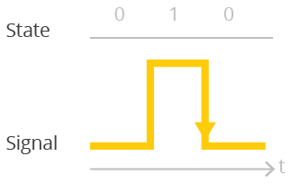
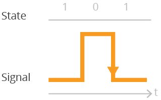
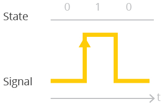
Polarity and Edge event are correlated when Edge Event is set to either PEE_HL or PEE_LH, because:
- Polarity defines whether 1 indicates a pulse and 0 indicates no pulse, or vice versa.
- PEE_HL / PEE_LH define whether sampling is triggered by a change from 1 to 0, or from 0 to 1.
This means that flipping the setting of either polarity or Edge Event HL/LH, reverses the conditions when sampling is triggered, as shown in the following table.
|
If Edge Event is this value |
and if Polarity is this value |
Then Transmission will be triggered by: |
|
|
PEE_HL |
PPOL_ACTIVE_HIGH |
A change from no pulse to pulse |
 |
|
PPOL_ACTIVE_LOW |
A change from pulse to no pulse |
 |
|
|
PEE_LH |
PPOL_ACTIVE_HIGH |
A change from pulse to no pulse |
 |
|
PPOL_ACTIVE_LOW |
A change from no pulse to pulse |
 |
|
Appendix B: Description of an Output Channel’s Advanced Settings
To set the advanced settings of an output channel, configure the parameters described in this section.
Active
|
Description: |
Defines the channel’s state as enabled or disabled. |
|
Options: |
AS_OFF – Default. Channel is inactive/disabled. No samples will be recorded. AS_ON – Channel is active/enabled. Samples will be recorded. AS_ON_HOLD – Channel is active and waiting for a trigger to instantiate.
|
location
|
Description |
Defines which pin number on the device’s digital connector port 3 is receiving signals from the sensor. On the Wavelet V2™ device, an additional pin for digital input is on connector port 1 (analog) of the device. |
|
|
Notes |
Important: Locations that are appropriate for your device might vary, depending on the device type. Use the detailed pinout information for your device to select the appropriate value for Location. |
|

|
Value for Location |
Function |
Connector Port on Device |
Pin # on Connector Port |
Found in Which Device |
|
PL_DIGITAL_IO_PCNT_0, PL_MCU_PCNT_0 (old name) |
PCNT, Edge, Periodic, output |
Digital |
1 |
Wavelet 4™, Wavelet V2™, Wavelet Ex™, Wavelet 4R™ |
|
PL_DIGITAL_IO_PCNT_1, PL_MCU_PCNT_1 (old name) |
PCNT, Edge, Periodic, output |
Digital
|
3 |
Wavelet 4™, Wavelet V2™, Wavelet Ex™, Wavelet 4R™ |
|
PL_DIGITAL_IO_2, PL_ACMP_0 (old name) |
Edge, Periodic, output |
Digital
|
5 |
Wavelet 4™, Wavelet V2™, Wavelet Ex™ |
|
PL_DIGITAL_IO_3, VLSense1 (old name) |
Periodic, output |
Digital
|
2 |
Wavelet V2™ |
|
PL_DIGITAL_IO_4, VLSense2 (old name) |
Periodic, output |
Analog |
2 |
Wavelet V2™ |
|
PL_IOEXT_GPIO_1 |
DO NOT USE – Unsupported by hardware and/or firmware |
|||
|
PL_IOEXT_GPIO_2 |
||||
|
PL_IOEXT_GPIO_3 |
||||
|
PL_IOEXT_GPIO_4 |
||||
|
PL_ADS_GPIO_1 |
||||
|
PL_ADS_GPIO_2 |
||||
|
PL_ADS_GPIO_3 |
||||
|
PL_ISO_INPUT_A |
||||
|
PL_ISO_INPUT_B |
||||
|
PL_ISO_OUTPUT_A |
||||
|
PL_ISO_OUTPUT_B |
||||
type
pull
|
Description: |
Specify the function of the pull-up resistor used in the device to ensure a known state for a signal. |
|
Options: |
PPULL_UP – Select this if the resistor raises the voltage to 2.8 volts PPULL_DOWN – Select this if the resistor lowers the voltage to ground PPULL_NONE – This is the default setting. Change this to PPULL_UP or PPULL_DOWN when configuring channel parameters. |
|
Schematic diagrams: |
|
Output_pulse_count
|
Description: |
The number of signal-cycles to send as the result of a Threshold action. Refer to PT_OUTPUT_DRIVE. |
output_time_high
|
Description: |
How long, in ms, to send an electrical signal in a signal-cycle. Refer to PT_OUTPUT_DRIVE. |
output_time_low
|
Description: |
How long, in ms, to refrain from sending an electrical signal in a signal-cycle. Refer to PT_OUTPUT_DRIVE. |
Appendix C: Digital Connector Pinouts
The digital connector in the WA1111 and WA1111-V2 is port 3. The port is an M12 5-pin male panel connector with 3 digital inputs for WA1111 and 4 digital inputs for WA1111-V2. Download the WA1111 and WA1111-V2 Pinouts PDF.
The connectors in WA3888 are on Ports 1, 2, and 3. Each port is an M12 8-pin male panel connector. Download the WA3888 Pinouts PDF.