Contents
Introduction to Analog Channel Advanced Configuration
Analog sensors that produce current output
Analog sensors that produce voltage output
Accessing an Analog Channel’s Advanced Settings
Description of an Analog Channel’s Advanced Settings
Introduction to analog channel advanced configuration
Most device configuration actions are performed in Transmission Interval and the Stream Management sections of the Ayyeka graphic user interface (GUI). However, certain advanced configuration tasks can only be done using the Device Advanced Configuration hierarchical tree, available also through the GUI. One of those tasks is the advanced configuration of a device’s analog channel, which is a channel that produces a continuous output signal.
Note that the analog channel configuration you set through the Advanced Configuration tree is applied to the channel in addition to the other channel settings you set graphically through the UI (such as Threshold definitions, described in Configure Data Stream Thresholds).
What is an analog sensor?
By changing its internal state (such as resistance) in response to an external stimulus (such as heat), an analog sensor produces a continuous output current or voltage that is proportional to the quantity being measured.
Analog sensors are useful for measuring physical quantities such as temperature, pH level, pressure, etc., because these tend to be continuous in nature.
Two types of analog sensors are supported:
Analog sensors that produce current output
The output of analog sensors of type current is a continuous electric current. For example, if the sensor is a 4-20 mA sensor for measuring pH, its current flow would be lowest (4 mA) when pH is 0 (most acidic), increasing continuously and linearly as acidity decreases, with the current flow reaching its highest value (20 mA) when pH reaches 14 (most basic).
Note: For instructions how to connect an analog 4-20 mA sensor to the device, see Connecting a 4-20mA Sensor.
Analog sensors that produce voltage output
The output of analog sensors of type voltage is a continuous voltage. For example, if the sensor is a 0 – 5V sensor for measuring pH, its voltage would be lowest (0V) when pH is 0 (most acidic), increasing continuously and proportionally as acidity decreases, with the voltage reaching its highest value (5V) when pH reaches 14 (most basic).
Data smoothing
Raw data is obtained from the analog sensor by sampling it at a high frequency every configurable number of minutes. To smooth out short-term fluctuations in the data and highlight longer-term trends, Smoothing the raw data points is done in three stages:
- Stage 1: Apply a moving average to the raw data points that are the actual readings from the sensor. The resulting values are now considered the raw data points.
- Stage 2: Apply a graph-normalizer to the data points that are the output of stage (1). The resulting values are now considered the raw data points.
- Stage 3: Apply a moving average to the data points that are the output of stage (2). The resulting values are now considered the raw data points.
All three stages are optional. You can elect to skip any one, two, or all three of the stages.
For an explanation of the moving average mechanism and graph-normalizer mechanism, refer to Moving average and graph-normalizer.
Accessing an analog channel’s advanced settings
To access an analog channel’s advanced settings:
- In the left pane, click Devices.
- In the Sites Tree pane, select the device.
- In the right pane, click the Configuration.
- In the Stream Management table, locate the desired stream’s channel number in the # column. For example, the channel number might be 0.
- Scroll down past the Stream Management table, and then click Advanced Device Configuration.
- Check the parameter values for all sample groups. For details of the parameters and their values, see Configuring SampleGroup (Group of Sensors in a Channel).
- In the Advanced Device Configuration tree, click Analog to expand it.
- Click Channel to expand it.
- In our example, select 0 under the Channel node because in Step (4) we decided to configure that channel.
- Define the channel settings in the parameter nodes nested under the channel number node, as described in Description of an Analog Channel’s Advanced Settings.
- Save the configuration changes, and then validate that the device rebooted by doing the following steps:
a. Click Devices in the left pane, and then select the device in the Sites Tree pane.
b. In the right pane, click the Commands tab. You will see a Reboot command after a few seconds.
c. If no Reboot command is displayed, click Actions > Reboot in the Device Information pane to manually reboot the device.
Both the configuration changes and the reboot will take effect after the device contacts the server.
Description of an Analog Channel’s Advanced Settings
To set the advanced settings of an analog channel, configure the parameters described in this section.
active
|
Description: |
Defines the channel’s state as enabled, disabled, or waiting for an event trigger. |
|
Options: |
Steps to Put a Channel On Hold: In FW version 2.320 and newer, this value cannot be used. If a channel needs to be on hold, do the following steps:
|
channel_type
|
Description: |
Defines which pin number on the device's analog input connector (Port 1) is receiving signals from the sensor, as well as the data type: Voltage or Current. |
 |
|
Options: |
|
|
|
Notes: |
CT_VOLTAGE_LOW values are deprecated and are no longer in use. Pin 8 is GND. For detailed analog connector pinout information, see the back pages of the Quick Start Guide for your device. |
|
sample_power_source
|
Description: |
Defines the sensor’s expected power supply. |
||
|
Options: |
|
||
|
|
||
|
|
||
|
Notes: |
To select other power sources, contact support@ayyeka.com. Most sensors require at least 6V, so you will typically need either PS_EXT1_BOOST or PS_EXT2_BOOST. In Wavelet 4R™, the single panel connector port has connector pins for analog, serial, and digital. In this device, use PS_EXT1_BOOST. In general, when there are two or more Analog sensors, they can each share the same Wavelet output power source (such as Pin 3). However, when the Analog sensors have different wake-up times, or they are in different Sample Groups that have different Sample Intervals, it is recommended to connect the sensors to different power source pins. For detailed analog connector pinout information, see the back pages of the Quick Start Guide for your device. |
||


ratiometric
This parameter is intended for advanced configuration of ratiometric sensors. For further details, contact support@ayyeka.com.
ratiometric_scale
This parameter is intended for advanced configuration of ratiometric sensors. For further details, contact support@ayyeka.com.
filter_type
|
Description: |
Specifies the filtering method used to reduce noise from the sensor’s electrical output. The electrical output signal, produced by the sensor, is sampled by the device at each sampling interval. The filter type parameter specifies which method of noise reduction calculation to use. In the diagram below, figure B illustrates the effect of noise creeping into the signal. Figure C illustrates the result of applying an average to filter out the noise. |
|
Options: |
|
|
|
 |
|
filter_sample_count
|
Description: |
Specify the number of times the device samples the sensor, at the highest sampling frequency possible, after the Wakeup_time period. |
|
Options: |
Specify a number. The default value is 0. |
wakeup_time_ms
|
Description: |
Specify the length of time, in milliseconds, that the sensor is on before starting to sample. This parameter defines the sensor stabilization time. Note that the frequency at which the sensor is turned on, is determined by the sample_interval. |
| Example | If the wakeup time interval is 500ms, the device starts sampling the sensor 500ms after it is turned on, at the highest sampling frequency that produces as many readings as defined in Filter_sample_count. |
sample_interval
|
Description: |
The rate, in seconds, at which the device wakes up the sensor and samples it for data. |
|
Example |
If the sample_interval is 900 seconds, then the sensor is turned on every 15 minutes (and remains turned on for the period of time defined in Wakeup_time_ms, plus the time needed to sample the sensor as many times as defined in Filter_sample_count). |
|
Note: |
The sample_interval value is relevant only when the Firmware is older than version 2.3x and when Group is set to 0. Otherwise, this parameter is ignored because sampling is done only for a group of channels. |
sample_interval_type
|
Description: |
The type of time interval for device sampling of the sensor – whether it is rounded to whole minutes, or not. The sample interval starts from the boot time. |
|
Options: |
Suppose that you set the sample_interval to 60 seconds. The device boots at 11:01:30. In that case:
To avoid data loss, do not use INTERVAL_SYNCED if the sample_interval for the group is less than 60 seconds.
|
|
Note: |
The sample_interval value is relevant only if Group is set to 0. |
graph_normalizer_a, graph_normalizer_b, graph_normalizer_c
|
Description: |
The graph is normalized by setting three parameters a, b, and c in graph_normalizer_a, graph_normalizer_b, and graph_normalizer_c respectively. Specify whether to apply the second of three optional Data smoothing measures to the data points. This second stage employs a graph-normalizer mechanism. The graph normalizer is defined by setting three parameters: a, b and c. To every data point value x (where x is the result of applying a Moving average), we apply the following normalizer function: y=(a/b)*x + c Note: You can alternatively set these a, b, c values by changing the Conversion Formula in the Stream Eng. Units Converter Configuration window, as described in Changing the Conversion Formula in Editing Raw Data and Applying a Transformation. |
|
Important |
If you elect to apply a graph normalizer, then the output of the process is henceforth considered the raw data – both as regards the display of the raw data in the UI, and as regards further manipulation of raw data. For example:
|
|
Options: |
a = 1 In effect, the data point values remain unchanged.
|
|
Example: |
To transform 4 – 20 (mA) to 0-14 (pH), set: a = 7 |
graph_mean_count
|
Description: |
Specify whether to apply the last of the optional Data smoothing measures to the raw data points from the sensor. This last stage again employs a Moving average mechanism, but its degree of smoothing is determined by the value you specify in graph_mean_count. Specifically, graph_mean_count defines how many recent data points to include when calculating the final Moving average value of a data point. The values obtained after applying this final smoothing measure, appear as the raw sample values in the Samples table. |
|
Options |
|
|
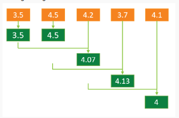
A moving average is a calculation that creates a series of averages of different subsets of the full data set. The moving average of a given data point is the mean of the Z-most recent data points, where Z is the mean_count number. For example, if the mean_count=3, then the moving-average of a given data point is the mean of the following 3 data points: the given data point and the two preceding data points. Important: If you elect to apply a moving-average to raw data, then the output of the process is henceforth considered the raw data – both as regards the display of the raw data in the UI, and as regards further manipulation of raw data. For example:
|
|
|
Schematic diagram: |
Moving average = 3
|
graph_level_index
This setting is populated by the Thresholds definitions set in the GUI.
graph_level_count
This setting is populated by the Thresholds definitions set in the GUI
group_priority
|
Description: |
If several sensors are assigned to the same Group, this parameter determines in which order the sensors will be sampled. The channel with the highest group_priority number is sampled first, then the channel with the second highest Group_priority number, etc. |
Analog Input Lowpass Filter
|
Description: |
A filter is a circuit that removes, or “filters out,” a specified range of frequency components.t separates the signal’s spectrum into frequency components that will be passed (audio waveform) and frequency components that will be blocked ("noise"). A low-pass filter passes low frequencies and blocks high frequencies. A high-pass filter passes high frequencies and blocks low frequencies. This parameter is in firmware 2.388 and newer. |
|
Options: |
|
| Note: | Analog Input Lowpass Filter is only available in firmware 2.388 and newer. |