Contents
Overview of the KEP SUPERtrol Flow Computer
Communication Interface for KEP sensors
Serial Wiring
Accessing a Serial Channel’s Advanced Settings
Description of Serial Configuration Parameters
Data Handling by the Serial Sensor
Analog Wiring - One KEP Unit to One Wavelet
Digital Wiring - One KEP Unit to One Wavelet
Overview of the KEP SUPERtrol Flow Computer
The KEP™ SUPERtrol™ Flow Computer is a sensor that satisfies the instrument requirements for a variety of flowmeter types in liquid, gas, steam and heat applications.
Multiple flow equations are available on a single instrument with many advanced features. The KEP sensor typically reads Mass Flow Rate, Temperature (Saturation), Pressure, Demand, Demand Time, Demand Date, Grand Mass, and Demand Last Hour.
For details about the KEP SUPERtrol Flow computer, see KEP SUPERtrol Flow Computer.
Serial Topology
RS-232 and RS-485 are standard protocols for serial data transmission. Two KEP sensors at the same site can be connected to a single Wavelet by RS232.
Warning:
Some KEP devices support connecting two devices to one Wavelet, while other KEP devices do not and might be damaged.
Verify with the manufacturer that your KEP devices support multiple devices to one master device.
Communication Interface for KEP sensors
The KEP sensor uses a proprietary protocol (not Modbus), that is supported by the Wavelet. The sensors use the following default manufacturing configuration on the serial port:
-
Default address: 01
-
Baud rate: 9600
-
Data Bits: 8
- Stop Bits: 1
- Parity: None
The KEP sensor parameters, such as baud and parity, can be changed, so it is important to check the KEP parameters in the KEP sensor Setup Mode before you configure the Wavelet. The sensor and the Wavelet must both use the same parameter values.
Prerequisites
- KEP SUPERtrol Flow Computer is intended primarily for use with FAI Pro. If you need to use the sensor with your FAI Local on-premises system, contact support@ayyeka.com.
- The KEP SUPERtrol Flow Computer is for Wavelet 4™ and Wavelet V2™.
- You must have Firmware version 2.301 or newer on the Wavelet. Contact support@ayyeka.com to apply the KEP firmware, if needed.
- In FAI Pro or FAI Local user interface, the KEP template must be applied to the Site where the KEP SUPERTROL Flow Computer will be installed. Contact support@ayyeka.com to send you the KEP template.
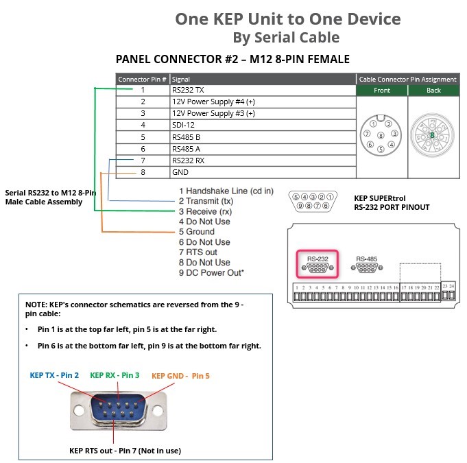
Serial Wiring
One KEP Unit to One Wavelet
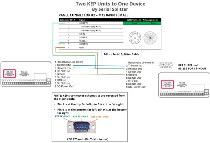
Two KEP Units to One Wavelet
Serial Configuration
Accessing a Serial Channel’s Advanced Settings
Follow the steps to access a channel’s advanced settings.
Both the configuration changes and the reboot will take effect after the device contacts the server.
Description of Serial Configuration Parameters
bus_baud
|
Description: |
Defines the baud rate of the serial bus. The baud rate of the master and the slaves must be the same. Select the baud rate that is given in the hardware specifications of the sensor. |
|
Note: |
All channels in the same group must have the same baud rate. |
|
Typical Value: |
9600 |
bus_parity
|
Description: |
Bit parity is used to indicate if all data was transmitted successfully. The bit parity of the master and the slaves must be the same. Select the bus parity that is given in the hardware specifications of the sensor. |
|
|
Typical Value: |
BUS_PARITY_NONE |
|
interface_type
|
Description: |
Defines the type of serial port. Select the type of serial port that is given in the hardware specifications of the sensor. |
|
Typical Value: |
IT_RS232 |
sample_handler
|
Description: |
Uses the KEPmeter communication protocol. |
|
Typical Value: |
SH_KEPMETER |
wake_time_ms
|
Description: |
Specify the length of time, in milliseconds, that the sensor needs to completely power up and calibrate before the Wavelet requests a sample from the sensor. |
|
Typical Value: |
Because the KEP sensor is always on, you must use 0. |
slave_addr
|
Description: |
The KEP sensor number (0-99) is the device address. Use the device address that is given in the hardware specifications of the KEP sensor. |
read_addr
|
Description: |
xx 00-99 Command group See the Universal Protocol User's Manual for a complete listing of the commands set supported. For the command group and its specific commands, see the following manual:
Important:
|
|
Example: |
For Time value, set read_addr to 0012 (xx=00, yy=12) |
group
|
Description: |
group must be assigned to a group. 1 – This channel is associated with Sample Group 1. 2 – This channel is associated with Sample Group 2. |
|
Typical Value: |
1 2 |
group_priority
|
Description: |
If several channels are assigned to the same group, this parameter determines in which order the sensors will be sampled. The channel with the highest group_priority number is sampled first, then the channel with the second highest group_priority number, and so forth. |
active
|
Description: |
If several channels are assigned to the same group, this parameter determines in which order the sensors will be sampled. The channel with the highest group_priority number is sampled first, then the channel with the second highest group_priority number, and so forth. |
|
Typical Value: |
AS_ON |
sensor_power_source
|
Description: |
The power source of a KEP unit is always external. |
|
Typical Value: |
PS_INT |
reset_delay
|
Description: |
Value to multiply the result by. The default value is 1000. Example: If the result from the device is 0.5 and
|
data bits
|
Description: |
Data is transmitted as a series of seven, eight, or nine bits with the least significant bit sent first. Select the number of data bits that is given in your hardware specification. |
|
Options: |
DB_7 – 7 data bits DB_8 – 8 data bits DB_9 – 9 data bits |
|
Typical Value: |
DB_8 |
stop bits
|
Description: |
The stop bit signals the end of a data packet transmission. Select the number of stop bits that is given in your hardware specification. |
|
Options: |
SB_1 – 1 stop bit SB_1_5 – 1.5 stop bits SB_2 – 2 stop bits |
|
Typical Value: |
SB_1 |
graph_mean_count
|
Description:
|
Specify whether to apply the last of the two optional data smoothing measures to the raw data points. This last stage again employs the Moving average mechanism, but its degree of smoothing is determined by the value you specify in graph_mean_count. The values obtained after applying this final smoothing measure appear as the Raw Values in the Samples table.
|
Data Handling by the Serial Sensor
The serial sensor obtains raw data by sampling it every configurable number of minutes. You can smooth out short-term fluctuations in the data and highlight longer-term trends by using data smoothing and moving average techniques.
For details, see the data smoothing and the Moving average mechanisms.
TROUBLESHOOTING
Log files with information about Wavelet-KEP communication are in the FAI Pro and FAI Local UI. Alternatively, you can connect the Wavelet to a laptop by using a USB cable, and then use PuTTY commands to interrogate and troubleshoot the device. For details, see Connect to Device by Using PuTTY.
To set up device-KEP sensor tracing from the UI:
-
Click Devices in the left panel.
-
In the Sites Tree pane, select the device.
-
In the right pane, open ADVANCED DEVICE CONFIGURATION, and then click the Configuration tab.
-
Open the SysHealth section, and then click system log level.
-
Click the value of system log level. For example, click TRACE_LEVEL_ERROR.
-
Click Set Setting, select TRACE_LEVEL_DEBUG, and then click Submit.
The configuration change will take effect after the device contacts the server.
The following table describes the trace output that you might get when troubleshooting KEP sensors.
|
Trace level |
Trace output |
Explanation |
Possible causes |
|
Debug |
kepmeter - device did not echo, check device_address / connection. |
Only the device that data was sent to should echo what was sent to it. |
The device is not powered up. The device is not connected to Wavelet. Device number (in device Setup) and slave_addr do not match. |
|
Debug |
kepmeter - echo from the device is different than what was sent. |
The echo from the device is not as expected. |
Check the device connection. |
|
Debug |
kepmeter - no response for command execution. |
The device did echo but got no response after the command was executed. |
|
|
Debug |
kepmeter - response from the device is not as expected. response ... |
The response from the device is not valid. |
The device is trying to read a command (xxyy) that is not implemented on the device. The device is trying to reset a value that is read-only. |
|
Debug |
kepmeter - about to reset the value at (command), time is (UTC time). |
About to send the command to reset the command value. The time is in UTC standard. |
|
|
Debug |
kepmeter - succeeded on try (number) |
The Wavelet tried several times to execute a command. The command was executed on the X try. |
|
|
Debug |
kepmeter - checking if time to reset value. time now... kepmeter - reset set time: ... reset timeout... |
These two lines are printed together to help debug the reset value issues |
|
|
Debug |
kepmeter value = |
value (as string) read from a device. |
|
|
Warning |
kepmeter - Failed to execute command: ... |
Failed to execute command (xxyy) |
The device does not support this command. |
|
Log |
kepmeter - successfully reset value. |
The reset value was done. |
|
APPENDIX
To configure the analog and digital channels of the Wavelet, follow the steps to access a channel’s advanced settings, except select “analog” or “digital” instead of “serial”.
Analog Wiring - One KEP Unit to One Wavelet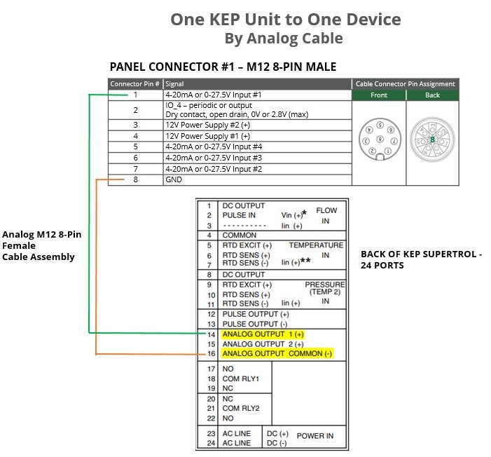
Analog Configuration
Configure the KEP analog sensor in the UI as you would any analog sensor.
Digital Wiring - One KEP Unit to One Wavelet 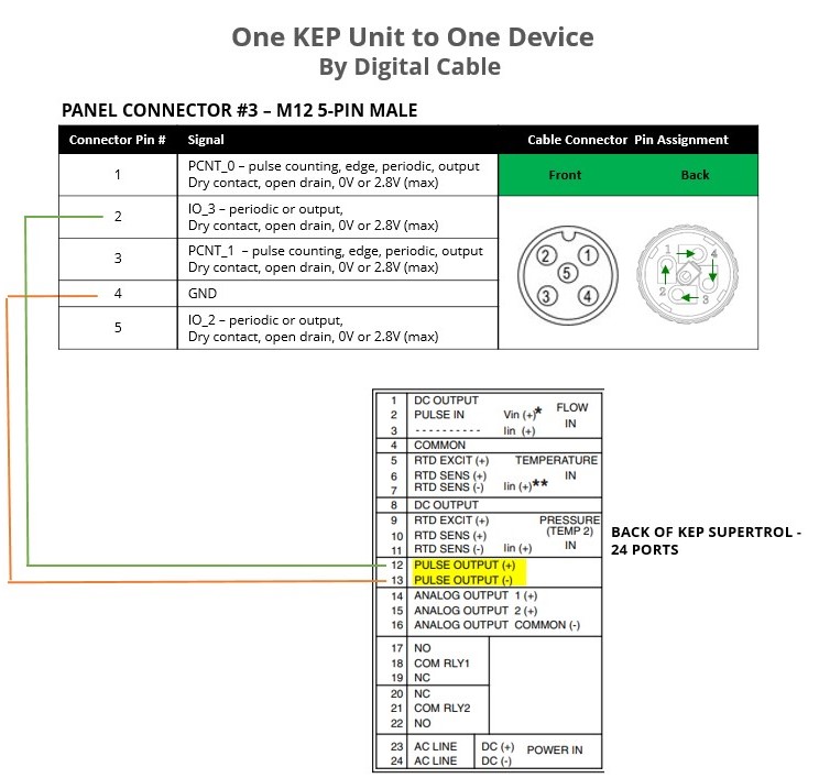
Digital Configuration
Configure the KEP digital sensor in the UI as you would any digital sensor.